background image

Oxygen Monitor SGM7.2.4/7.2.6                                                                                           6 Composition


17


6.1.2 

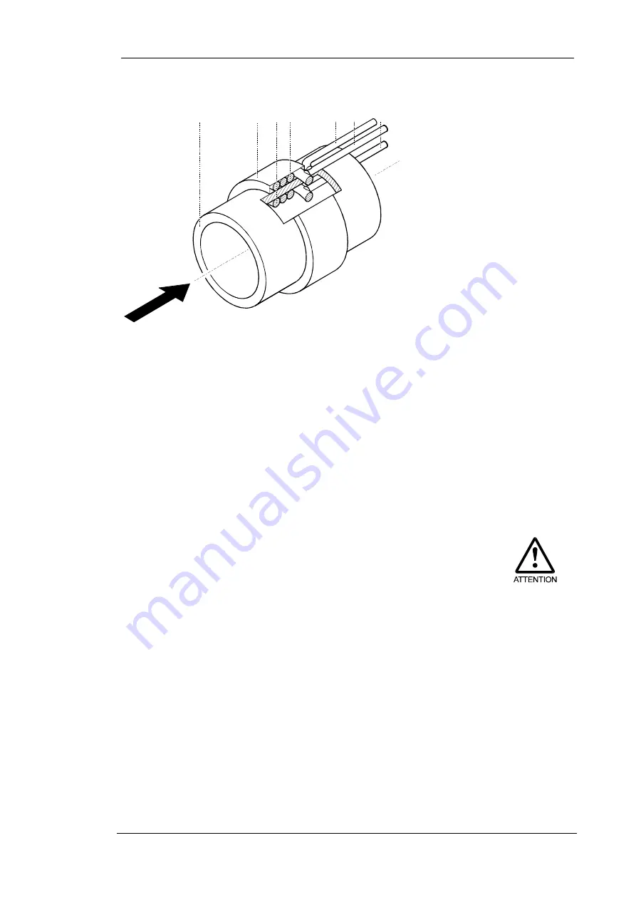
Construction principle of the solid electrolyte sensor 


1

2

5

6

7

3

4

Measurig Gas


Fig. 2:  

Composition of the solid electrolyte sensor 


The  measuring  cell  (sensor)  consists  of  a  tube  made  of  zirconium 
dioxide (2/1) with two platinum electrodes. The measuring electrode 
is inside the tube (2/3). The reference electrode (2/4) is located on 
the outside of the tube and has a constant electrode potential. The 
electrodes  and  the  ceramic  tube  form  a  galvanic  solid  electrolyte 
measuring cell. 

Measuring cell 
(sensor) 

In  order  to  gain  a  higher  oxide  ion  conductivity  of  the  zirconium 
dioxide  tube,  the  sensor  is  heated  to  750°C.  This  also  avoids 
interfering reactions with combustible components of the measuring 
gas at the electrode caused by chemical unbalances. A thermocouple 
(2/5)  inside  the  measuring  cell  determines  the  actual  electrode 
temperature. A regulator ensures a constant temperature. 

Sensor heater 

The heated measuring cell produces thermal energy. Therefore, the 
SGM7.2.4 must not be covered.  


1  Ceramic tube 
2  Ceramic cover of reference 

electrode 

3  Measuring electrode 
4  Reference electrode 
5  Thermocouple 
6  Connecting wire of 

reference electrode 

7  Connecting wire of 

measuring electrode 


Содержание SGM7.2.4

Страница 1: ...nsoren Elektronik GmbH Am Koppelberg 21 17489 Greifswald Germany 49 3834 8309 00 Fax 29 E mail info zirox de ZIROX Oxygen Measuring Systems SGM7 2 4 SGM7 2 6 Oxygen Measuring Device For Reflow Soldering Systems ...

Страница 2: ...2 ...

Страница 3: ... 2 6 Manual Oxygen Measuring Device For Reflow Soldering Systems Range 2 10 5 10 vol ppm Power supply 100 240 V 47 63 Hz Operating hour counter Indication of maintenance interval for filter change depends on pump mode ...

Страница 4: ...neral data 13 5 4 Interface data 14 5 4 1 Pump control 15 6 Composition of the oxygen monitor SGM7 2 4 16 6 1 General composition 16 6 1 1 General overview 16 6 1 2 Construction principle of the solid electrolyte sensor 17 6 1 3 Electronic data processing 18 6 2 Usage and connection elements 19 6 2 1 Current supply 19 6 2 2 Front 19 6 2 3 Rear 20 7 Installation and initiation 21 7 1 Installation c...

Страница 5: ...aintenance overhaul and storage 31 9 1 General instructions 31 9 2 Replacement of the equipment fuse 31 10 Appendix 32 10 1 Activated carbon filter description and application notes 32 10 1 1 Filter construction 32 10 1 2 Application and operation of the filter 32 10 1 3 Replacement of activated carbon 33 10 1 4 Technical data 34 10 2 EU Declaration of conformity 35 10 3 Warranty conditions 36 11 ...

Страница 6: ...dment service If the manufacturer modifies the SGM7 2 4 with the aim of making technical improvements the user is responsible for inserting the additional or updated pages supplied Proper operation of the SGM7 2 4 can only be ensured if the contents of this manual are known Therefore all chapters of this manual must be read carefully prior to operating the SGM7 2 4 The values on the device display...

Страница 7: ...anger The degree of the damage depends on the circumstances and the actions of the persons involved In case of disregard destruction or damage of the SGM its single components or other material assets as well as minor injuries may result Symbol for proper handling This symbol appears where the manual refers to the adherence to rules instructions and proper operation In case of disregard damage or ...

Страница 8: ...oduction as well as plant construction production processes of electronic components under buffer gas The introduction of explosive gas compounds high concentrations of halogens or sulphuric gases e g SO2 into the SGM7 2 4 is not permitted The contact of the SGM7 2 4 with siliconic or phosphoric compounds is not permitted either The SGM7 2 4 Functions measures and indicates the oxygen concentratio...

Страница 9: ...peration only see chapter 2 The SGM is to be installed operated and serviced by trained staff only The SGM is to be connected to an isolated ground socket Schuko socket with the supplied cable Explosive gas compounds halogens in high concentration and sulphuric gases e g SO2 are not permitted to be measured by this SGM7 2 4 Due to the high operation temperature of the sensor the SGM produces a lot...

Страница 10: ...xygen at the reference electrode in dry air in Pa pO2 meas gas partial pressure of the oxygen at the measuring electrode in the measuring gas in Pa The sensor of the SGM7 2 4 is based on the conductivity of oxide ions in a special ceramic substance zirconium dioxide with stabilizing additions The conductivity of these oxide ions increases exponentially with the temperature and reaches a sufficient...

Страница 11: ...ygen concentration is valid for measuring gases with free oxygen as well as for reducing gas compounds in which oxygen only exists in bound form e g in H2 H2O or CO CO2 compounds 4 2 1 Gas flow rate The constant flow rate of the measuring gas is ensured by an internal pump It can be chosen between HIGH 35 l h maintenance interval runs 3 times faster than in the LOW mode and LOW 8 l h 1 Different c...

Страница 12: ...g gas must be extracted where a formation of layers can be avoided The tube from the measuring point to the SGM7 2 4 must be as short as possible in order to avoid a change in the chemical balance in the tube All gas inlet and outlet tubes must be free of leaks If the measuring gas contains reducing components e g alcohol the concentration of free oxygen cannot be determined correctly as chemical ...

Страница 13: ...r pressure Max permitted temp of the gas 80 C p over measuring cell Approx 1 kPa 100 mm WS at 10 l h Working conditions 10 45 C rH 80 at 20 C Storage conditions 20 60 C rH 95 at 20 C Degree of protection IP40 5 2 Mechanical data Dimensions 135 x 100 x 240 mm Weight 3 kg Gas input Plug connection 6 mm Gas output Tube nipple 4 mm 5 3 Electrical engineering electronics 5 3 1 General data Current supp...

Страница 14: ...re in C Chart 2 Error indication Error code Description 0 ERROR0 Transmission error 1 ERROR1 Warm up 2 ERROR2 Cell temperature too low 3 ERROR3 Thermocouple defective 4 ERROR4 Operation hour meter run out Change filter or carbon then reset see manual 5 6 ERROR6 System error Analog output SGM7 2 4 Voltage output 0 2 10V potential free range adjustable SGM7 2 6 Current output 0 4 20 mA potential fre...

Страница 15: ...mp low P2CR P2CR pump high pCR pXCR scan pump state X 0 pump off X 1 pump low X 2 pump high Control input for pump relay 24 V DC internal inverse polarity protection and free wheeling diode Chart 5 Pin config for 7 pol socket and connection cable with plug 1 5 m long Pin Description Cable color 1 limit relay NC contact blue 2 limit relay NO contact brown 3 limit relay central contact green 4 pump ...

Страница 16: ...tion is shown in Fig 1 Fig 1 General composition of the SGM7 2 4 The measuring gas gets into the sensor by means of little overpressure at the inlet or the optional pump ingests the measuring gas In the first case the optional pressure reducer or needle valve at the gas inlet can be used to control the gas flow If the pump is installed the gas flow is controlled by a flow control of the pump ...

Страница 17: ...easuring cell Measuring cell sensor In order to gain a higher oxide ion conductivity of the zirconium dioxide tube the sensor is heated to 750 C This also avoids interfering reactions with combustible components of the measuring gas at the electrode caused by chemical unbalances A thermocouple 2 5 inside the measuring cell determines the actual electrode temperature A regulator ensures a constant ...

Страница 18: ...lock diagram illustrates the data processing Fig 3 Block diagram of the SGM7 2 4 Sensor Amplifier for Cell Voltage Heater Control Microcontroller Sensor Surveillance Pow er Supply 1 0 A 0 8 A Amplifier for Thermocouple Display Keyboard DC Output Relay Outputs RS 232 110 230 V 50 60 Hz Analog out ...

Страница 19: ...ed on the front of the SGM7 2 4 Depending on the size the measuring values are displayed either in vol or in vol ppm A green or orange light serves as operating indication depending on the chosen limit value and actual measuring value A red light points out certain operating or warning conditions see chap 8 1 4 A keypad is located on the right side of the front panel It serves the programming of t...

Страница 20: ...ection for pump control relay included the RS232 Interface the pump switch and the power switch are located on the rear panel The gas inlet is connected with the carbon filter The inlet of the filter is located on the front side The line cord is permanently fixed with the device It cannot be connected Fig 5 Rear of the SGM7 2 4 ...

Страница 21: ... the device 7 2 Set up of operating state A temperature compensation is required after the transportation of the SGM7 2 4 from cold surroundings to a site with higher ambient temperature or humidity A waiting time of about 2 hours before switching on must be considered 1 Install the SGM7 2 4 in the favored place see chapter 7 1 2 Connect point of measurement and places of gas inlet and outlet of t...

Страница 22: ... on the measuring conditions Material of the connecting tubes Low temperature of measuring gas Thick wall PVC hose Higher temperature of measuring gas Tygon R 3603 supplier e g Novodirekt Kehl Oxygen concentration of 100 ppm Stainless steel tube Silicone can cause measuring inaccuracies because of its oxygen permeability Therefore the manufacturer advises against a usage The measuring gas can also...

Страница 23: ...s the installation of a high quality needle valve Appropriate needle valves can be delivered by the manufacturer of the SGM7 2 4 For higher pressures of the measuring gas an additional pressure regulator is recommended which adjusts a pressure of approx 100 kPa 1 bar excess pressure 8 1 3 Data monitoring The SGM7 2 4 can be programmed with a limit value The relevant messages are delivered via rela...

Страница 24: ...pter 8 4 3 RANGE 4 FLOW 8 l h 5 FLOW 35 l h 6 Change filter 600 h or after period adjusted by customer 7 8 9 WARM UP Cell temperature too low wait after approx 15 minutes 750 C are reached 10 CELL TEMP Set temp 10 and 30 min 11 ERROR THERMOCOP Thermocouple broken 12 13 14 SELF TEST FAILED SGM7 2 4 Status 1 4 8 warnings only alarm relay active Status 2 3 warnings no alarm by alarm relay Status 9 14...

Страница 25: ...ange Max measuring value 21 0 vol or 210000 ppm Higher values on request This value corresponds to the terminal value of the analog signal e g 10 V Response time t90 1 99 sec Formed by arithmetical average of the measured value Limit value 0 99 99 vol or 0 999999 ppm Selectable as lower or upper limit value with the signs or Delay time of the limit value 1 99 sec Time to alarm when limit value is ...

Страница 26: ...tus on off by key and cell temperature The following status can be visualised by LED red flashing Error green OK yellow Limit value constantly pump off slow flashing pump low fast flashing pump high B Settings SETTINGS OPERATING HOURS GENERAL LIMIT ANALOG OUTPUT CALIBRATION RETURN B 1 Operating hours TOTAL TIME 90 h Total operating hours of the device CARBON FILTER CHANGE IN 145 h Time remaining t...

Страница 27: ...N OFF RETURN B 3 Limit values LIMIT VALUE VALUE 206400 ppm 0 999999 ppm resp 0 99 99 vol DELAY TIME 1sec 0 99sec RETURN B 4 Output ANALOG OUTPUT VALUE ppm O2 vol O2 O2 log10 RANGE 0 10 V 2 10V SGM7 2 4 0 20 or 4 20 mA SGM7 2 6 ZERO POINT 0 ppm END MARK 210000 ppm AVERAGE FACTOR 1sec 1 99sec RETURN B 5 Calibration CALIBRATION CALIBR ZERO POINT CALIBR SPAN GAS RETURN ...

Страница 28: ...RETURN 1 If this line is activated and key Enter is pressed for approx 3 sec the calibration value will be set to 0 0 B 5 2 Span gas calibration CALIBR SPAN GAS MEAS VALUE 206400 ppm Current measuring value SPAN GAS 1000 ppm Adjustable CALIBR SPAN WAIT 5 Calibration status CALIBR VALUE 1 00 Calibration value 2 RETURN 2 If this line is activated and key Enter is pressed for approx 3 sec the calibra...

Страница 29: ... approx 5 sec the calibration is finished Leave the calibration by pressing RETURN and ENTER Save it with YES 8 3 2 Span gas calibration Certified test gas oxygen concentration near future measuring conditions must flow through the device First select Calibration and then CALIBR SPAN GAS via keypad Set the test gas oxygen concentration Select CALIBR SPAN and start the calibration by pressing ENTER...

Страница 30: ...ge carbon filter reset interval Relatively high measuring value although a low value for the oxygen concentration is expected Gas flow too low Increase flow rate Micro leaks in the gas supply Check fittings Measurement is dependent on the throughput the smaller the flow the higher the value or vice versa Leaks in the measuring gas supply Check gas supply and fittings Measuring value is significant...

Страница 31: ...ufacturer for an overhaul If not in use the SGM has to be stored in the original packing if possible in a dry dust free room storage 9 2 Replacement of the equipment fuse Turn the SGM off and separate it from the net supply before replacing the equipment fuse The fuse 1 AT is located inside the device see arrow It has to be replaced by the same type After switch off the housing of the measuring ce...

Страница 32: ...fittings tube connection with seal ring have closing stoppers to keep the carbon inside The gas way is protected against carbon particles with a pre filter and a fine filter 2 filter paper discs in the outlet of the carbon filter 10 1 2 Application and operation of the filter Organic components of the test gas e g alcohols are adsorbed by the carbon After longer usage the cell voltage or the oxyge...

Страница 33: ...rs 7 Insert 2 fleece discs with tweezers into the tube connections on the gas inlet side 8 Insert 3 fleece and 2 filter paper discs on the gas outlet side fleece paper fleece paper fleece 9 Insert cover gas outlet into acryl glass tube by twisting it slightly 10 Refill the container with new activated carbon use funnel and compress it by knocking a piece of wood screwdriver or the like gently on t...

Страница 34: ...cal data Weight Approx 120 g Volume Approx 100 ml Duration of operation Depending on the components and the concentration of the adsorbed organic components e g approx 1 3 months at raw gas from a fermenting tank ZKG Carbon used Granulated or pelletized 1 3mm ...

Страница 35: ...Oxygen Monitor SGM7 2 4 7 2 6 10 Appendix 35 10 2 EU Declaration of conformity ...

Страница 36: ...is not permitted either A connection of ZIROX and non ZIROX products voids any warranty claims Warranty and warranty claims are only accepted if they are in accordance with the General Sales and Delivery Conditions of the manufacturer Warranty and liability claims for damage to persons and or property are void if they are subject to the following Normal wear and tear Improper use of the product Di...

Страница 37: ...Oxygen Monitor SGM7 2 4 7 2 6 11 Your notes 37 11 Your own notes and remarks ...

Отзывы: