22
UC5e IM Rev 2-1 July 2004
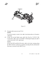
19.
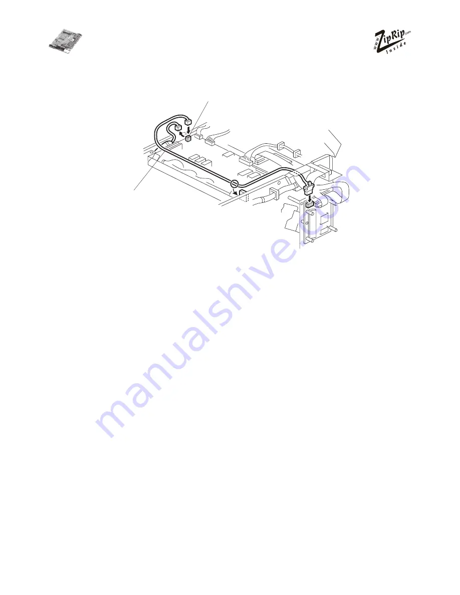
Disconnect the connector on CN114.
NOTE:
It is not necessary to remove the cable from the machine as it becomes
redundant.
20.
Locate the red and black power cable [A], Part No. VU5E 05 300.
Connect this cable CN114 on the MPU of the Digital Duplicator and J4
connector on the UC5E main board.
NOTE:
Secure the RED and BLACK power cable to the loom running along
the MPU with the 4 cables ties supplied, ensuring that the cable and the
loom does not catch on the MPU cover.
Figure 2f
[A]
CN114
Содержание UC5E
Страница 1: ...Installation Manual UC5e Revision 2 1...
Страница 2: ...2 UC5e IM Rev 2 1 July 2004...


