Track section module MX9 Page 5
4.
Addressing and programming the MX9
Assigning an address to (and often programming) a MX9 is necessary for ALL operating modes.
Only after the address has been changed from the default address 900 can the module be distin-
guished from other MX9 modules on the bus and used in operation!
CONNECTING the CAN BUS CABLE - POWERING THE MX9
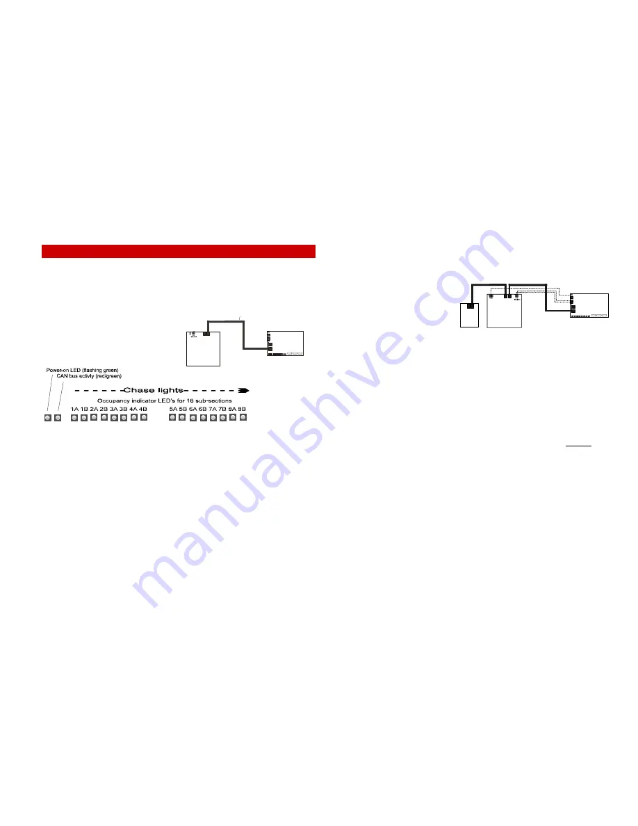
The processor is powered through the CAN bus,
which is made visible through the row of LED’s at
the back of the MX9: first by displaying the
EPROM version code and immediately after that
by flashing all 16 occupancy indicator LED’s in
sequence from left to right (chase lights).
The chase lights are also useful as an LED check. If a single LED does not light up briefly, it is most
likely defective. If none of them light up or uncontrolled flickering is observed, the module itself is de-
fective.
After that, the power-on control LED (far left) starts blinking green thereby indicating that the MX9 is
operational. The LED to the right starts flashing red/green indicating that there is activity on the CAN
bus.
ERROR DISPLAY:
- All 16 occupancy indicator LED’s flash in unison once per second:
Module is programmed to default address 900.
- LED’s 5A to 8B, which is the complete right LED group flashes as above
(at the same time the left LED group indicates a coded binary address):
Address conflict (same address is used on more than one MX9) !
No operation is possible unless this is corrected.
- Power-on LED, CAN bus LED and every second occupancy LED flashes:
EPROM is defective!
- CAN bus LED flashes, power-on LED remains dark:
Module needs to be repaired, defective EEPROM!
- CAN bus LED flashes rapidly, power-on LED flashes normal:
track power without valid DCC signal present!
ASSIGNING AN ADDRESS TO A MX9 MODULE:
Each MX9 requires its own address, which is used to access the track sections connected to it.
Each address must be unique, meaning the same address cannot be used for another MX9.
Each MX9 is programmed with the default address 900 at time of delivery. Allowable addresses that
can be used for actual layout operations
range from 901 to 963.
Programming an MX9 with one of these
addresses (901 to 963) is only possible:
•
if it is programmed first to the de-
fault address 900 (recognizable by
the 16 LED’s flashing in unison)
AND
•
the MX9 about to be programmed is the only track section module connected to the CAN bus
containing the address 900! Any number of other modules though (cab’s and accessory mod-
ules as well as all other MX9’s that already contain an address other than 900) may be con-
nected to the CAN bus during this procedure.
Please check the appropriate cab instruction manual (MX21, MX31 etc.) regarding the addressing
procedure.
DELETE AN EXISTING MX9 MODULE ADDRESS (RESETTING TO ADDRESS 900):
This is only possible if the MX9 in question is the only one connected to the CAN bus!
After the MX9 is programmed to address 900, it can be reprogrammed again to any of the available
addresses (901 to 963), see above.
Note: Deleting an address by Programming to the default address 900 does not initiate
a hard reset (resetting of all CV’s).
However: Programming CV #1 to 0 does initiate a hard reset and with it also changes the
address to 900.
READING OUT THE CURRENT ADDRESS:
Reading out an MX9 address is only possible if this is the only MX9 connected to the CAN bus.
Please check the appropriate cab instruction manual (MX21, MX31 etc.) regarding the read-out
procedure.
PROGRAMMING AND READING OF MX9 CONFIGURATION VARIABLES:
CV programming, in contrast to address programming, is also possible with many MX9’s connected
to the CAN bus, provided the MX9 address is known to the user. The MX9 address must be entered
first during this procedure so that only the CV’s of the intended MX9 are being reprogrammed.
Please check the appropriate cab instruction manual (MX21, MX31 etc.) regarding the read-out
procedure.
THE CONFIGURATION VARIABLES . . .
Because the meaning of the configuration variables partly depends on the operating modes (0 …4),
they are explained in the corresponding chapters 8….11.
C
A
N
C
A
N
MX9
C A
N
MX1
CAN
Command
Station
CAN
C
A
N
C
A
N
MX9
CAN
MX1
CAN
MX31
CAB
COMMAND
STATION
CAN
C A
N
Typical MX9 connection for the purpose of
address programming. Track power and CAN
bus is not necessary but may be connected if,
for example, it is practical for testing.
Содержание MX9V
Страница 22: ...Page 22 Track section module MX9 ...


