


Page 30 MS - SOUND decoders MS440 to MS990 and MN - NON-SOUND decoders MN170 to MN340
ZIMO digital systems offer a second level of communication for transmitting data to vehicles on specific
track sections. The most common application for this is the “signal-controlled speed influence” for stopping
trains and applying speed limits in 5 stages, with data sent to the track sections as needed in the form of
HLU cut-outs prepared by MX9 track section modules or its successors.
The speed limits “U” (Ultra-low) and “L” (Low speed) as well as the intermediate limits of the “signal-
controlled
speed influence” can be defined with configuration variables #51 to #55 as well as the acceler-
ation and deceleration values (momentum) with CV #49 and #50.
Please note that the signal-controlled acceleration and deceleration times in CV #49 and #50 are always
added
to the times and curves programmed to CV #3, #4, #121, #122 etc. Signal controlled accelerations
and decelerations compared to cab-controlled momentum can therefore only progress either at the same
rate (if CVs #49 and #50 are not used) or slower (if CV #49 and/or #50 contain a value >0), but never
faster.
It is of utmost importance for a flawlessly working train control system using the signal-controlled speed
influence that the stop and related brake section lengths are arranged properly and consistently every-
where on the layout. Please consult the MX9 instruction manual.
The deceleration (often CV #52 for “U” limit) and braking (CV #4 and #50) characteristics should be set
in a way, all locos come to a complete stop within about 2/3 of the stop section, which in HO is typi-
cally about 15 to 20 cm before the end of a stop section. Setting the loco up to stop precisely within the
last centimeter of a stop section is not recommended.
For a correct HLU behaviour of MS and MN decoders in case of "old" ZIMO command stations (MX1EC,
MX1 model 2000 or MX1HS) the CV #11 must be changed to 158 in the MX1(!) and the CV #27=1 must
be set (also in MX1). These three MX1 command stations must also not have an (almost) empty 3 V
button cell (recognizable by the fact that "data loss" is briefly shown on the MX1 display when the com-
mand station is started), because otherwise the changed value of CV #11 is not retained when the MX1
is switched off.
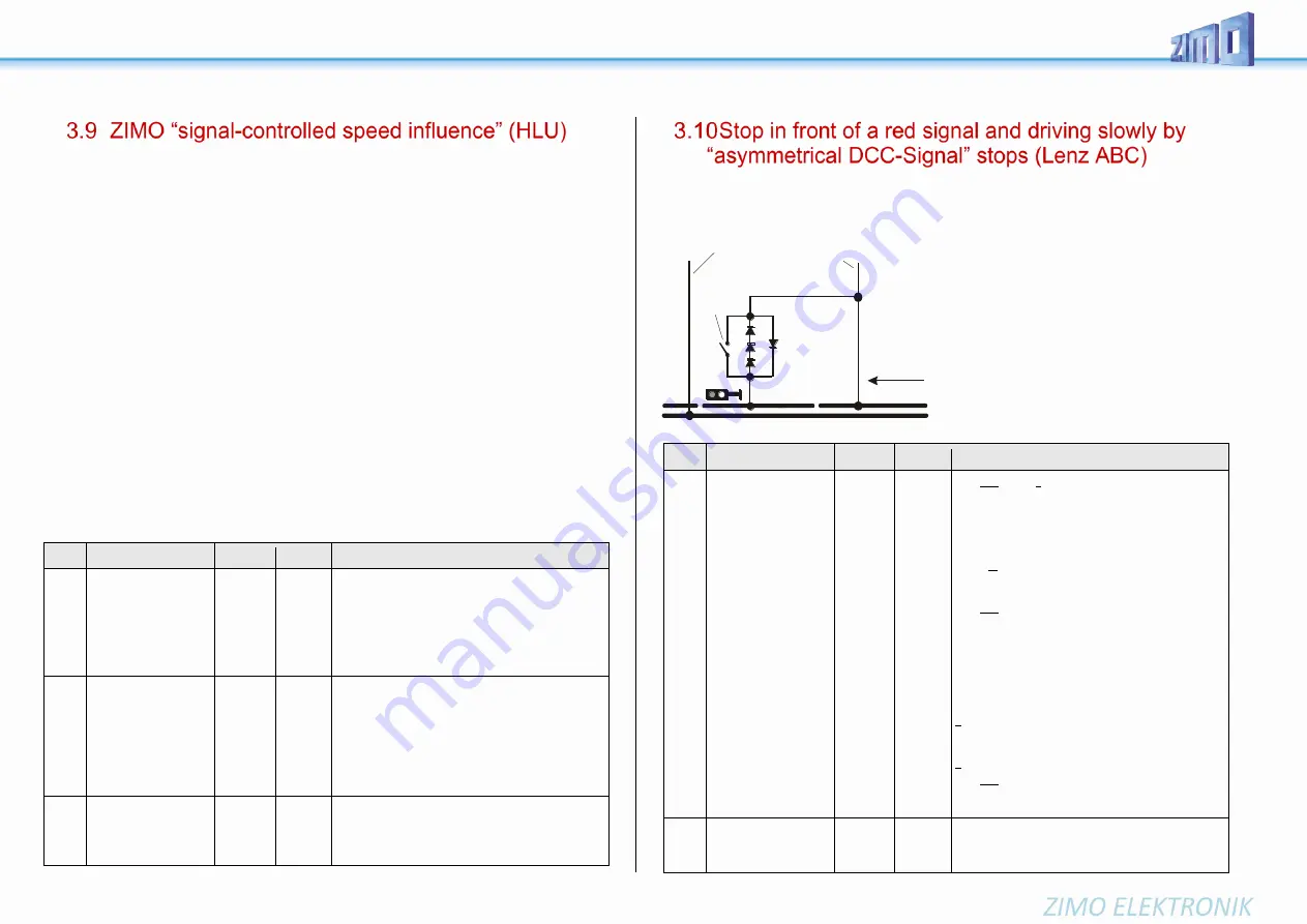
The
“asymmetrical DCC signal” is an alternative method for stopping trains (e.g. at a red signal). A
simple circuit made up of 4 or 5 commercially available diodes is all that is required.
Usually, the stop section contains 3 to 5 silicon diodes in series and one diode in parallel in the opposite
direction is the usual arrangement. The
different voltage drops across the diodes
results in an asymmetry of about 1 to 2 V.
The direction in which the diodes are
mounted determines the polarity of the
asymmetry and with it the driving direc-
tion a signal stop is initiated.
The asymmetrical DCC signal stop mode
needs to be activated in the decoder with
CV #27. Usually, bit 0 is set, that is CV
#27 = 1.
This results in the same directional con-
trol as the “Gold” decoder from Lenz.
CV
Denomination
Range
Default Description
#27
Position-dependent
Stopping
(“before a red signal”)
or driving slowly
by
“asymmetrical DCC sig-
nal“ (“Lenz ABC“)
All details and settings
are described in chapter
“Stop in front of a red
signal and driving
slowly...
“
or “ZIMO HLU
”
Automatic stopping
by DC brake section,
also:
“Märklin brake section”
Only possible, if analog
operation is locked; i.e.
if
CV #12, bits 0 und 4 = 0
0 =
ABC not
active,
HLU
active,
other
brake
sections
not active
Bit 0 and Bit 1 = 0: ABC not activated; no stopping
Bit 0 = 1: Stops are initiated if the voltage in the right
rail (in direction of travel) is higher than in the left rail.
This (CV #27 = 1) is the usual ABC application)
Bit 1 = 1: ABC stops are initiated if the voltage in the left
rail (in direction of travel) is higher than in the right rail.
If bit 0 or bit 1 =1 (only one of the two bits is set):
Stopping is directional, i.e. only in direction of travel to
the signal, travelling in opposite direction has no effect.
Bit 0 and Bit 1 = 1: Stops are independent of direction
of travel. See chapter “3.10 Stop in front of a red signal
and driving slowly
Bit 2
= 0: HLU train protection system (H, UH,…)
active
= 1: Effect (halt, limit) of HLU deactivated
Bit 4 - DC braking section, if polarity is reversed
0 = disabled 1 = enabled
Bit 5 - DC braking section, if polarity
is equal to direction of travel
0 = disabled 1 = enabled
Bit 4 and bit 5 = 1: stopping when
DC voltage (e.g. by a diode) independent
of the polarity (“Märklin brake section”)
#49,
#50
Acceleration,
braking time
0 - 255
0
Effect like HLU, therefore see chapter “3.9 ZIMO “sig-
nal-controlled
If those CVs are not used, CVs #3 and #4 are valid.
CV
Denomination
Range
Default Description
#49
Signal controlled
(HLU, ABC)
Acceleration
0 - 255
0
ZIMO signal-controlled speed influence method (HLU)
using MX9 or StEin:
or
with the “asymmetrical DCC signal” stopping method:
The value multiplied by 0.4 equals acceleration time in
seconds from stop to full speed.
Only CV #3
OR
CV #49 is used, depending on which
value is higher.
#50
Signal controlled
(HLU, ABC) braking dis-
tance
0 - 255
0
ZIMO signal-controlled speed influence (HLU) with
ZIMO MX9 track section module or StEin
or
when using the “asymmetrical DCC signal” stopping
method:
The value multiplied by 0.4 equals deceleration time in
seconds from full speed to stop.
Only CV #4
OR
CV #50 is used, depending on which
value is higher.
#51
#52
#53
#54
#55
Signal controlled (HLU)
speed limits
#52 for “U” (Ultra low)
#54 for “L” (Low speed)
#51, #53, #55 intersteps
0 - 255
20
40 (U)
70
110 (L)
180
ZIMO signal-controlled speed influence method (HLU)
using MX9 or StEin:
Defines the internal speed steps for each of the 5
speed limits generated by HLU.
H
alteabschnitt
Fahrspannung
vom Basisgerät (Zentrale)
Silicium-Dioden,
beispielsweise
1N5400x
(3 A - Typen)
Allgemeine Strecke
Fahrtrichtung
Schalter für
Aufhebung des Halts
bei “Signal
auf Fahrt"
Hinweis: 3 Dioden in Serie
ist die Mindestzahl, um bei
ZIMO Decodern zu wirken;
für Fremd-Decoder werden
manchmal 4 oder mehr
Dioden benötigt ! Da durch
die Dioden ein unerwünschter
Spannungsverlust entsteht,
verwendet man die Mindestzahl
je nach eingesetzten Decodern.
rot
Содержание MS450
Страница 5: ...MS SOUND decoders MS440 to MS990 and MN NON SOUND decoders MN170 to MN340 Page 5...
Страница 61: ...MS SOUND decoders MS440 to MS990 and MN NON SOUND decoders MN170 to MN340 Page 61...
Страница 85: ...MS SOUND decoders MS440 to MS990 and MN NON SOUND decoders MN170 to MN340 Page 85...
Страница 87: ...MS SOUND decoders MS440 to MS990 and MN NON SOUND decoders MN170 to MN340 Page 87...
Страница 88: ...Page88 MS SOUND decoders MS450 to MS990 ZIMO Elektronik GmbH Sch nbrunner Str 188 A 1120 Wien...


