INSTALLATION AND OPERATING INSTRUCTIONS:
GEH6000IL/GED6000IL
INSTALLATION AND OPERATING INSTRUCTIONS:
GEH6000IL/GED6000IL
28
29
EN / 2021-07-28
DDOC00212 / 0
EN / 2021-07-22
DDOC00212 / 0
Zimmer GmbH
•
Am Glockenloch 2
•
77866 Rheinau, Germany
•
+49 7844 9138 0
•
www.zimmer-group.com
Zimmer GmbH
•
Am Glockenloch 2
•
77866 Rheinau, Germany
•
+49 7844 9138 0
•
www.zimmer-group.com
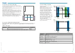
11.7 DeviceModes – behavior modes
The DeviceMode parameter can be used to adapt the behavior of the product to the application and the workpiece. You
can choose between control modes, for example for switching on the motor control (3), or operation modes, for example for
positioning the product (50).
The following sections describe the available DeviceModes.
INFORMATION
Note that different operation modes can be selected for products with -03 and -31 in the part number. See
sections
„Operation modes/movement profiles – GEH6000IL-03-B/GED6000IL-03-B“
movement profiles – GEH6000IL-31-B/GED6000IL-31-B“.
The control modes are the same for both series, see sections „DeviceModes – behavior modes“
and
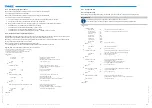
11.7.1 Control modes
Some gripper functions are controlled using what are called control modes.
DeviceMode
Remarks
1
Idle
2
Gripper reset
3
Switch on the motor control
5
Switch off motor control / stop movement
11
Jog mode
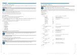
The available modes are identical across the series. They are listed below.
1 – Idle
An idle command for the product. When this mode is selected, no movement can be carried out.
2 – Gripper reset
Triggers a reset of the motor controller.
3 – Switch on the motor control
This switches on the motor control and activates the output stage.
This does not trigger any movement yet. The movement of the motor is not started until a move command is sent.
5 – Switch off motor control/stop movement
This switches off the motor control. The output stage is deactivated and any movements are stopped.
11 – Jog mode
In jog mode, the product moves in the corresponding direction (Base/Work) as long as the move command bits
(MoveToBase/MoveToWork) are set in the ControlWord.
Reversing the bits results in an immediate stop of the gripping movement.
This mode can be used for setting up the gripper positions, for example.
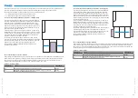
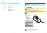
11.8 Referencing by homing
NOTICE
►
Before each homing command, make sure that the product is able to move freely and easily and that it cannot
be blocked by the gripper jaws or interfering edges.
When blocking, the reference position is set. A homing command is not permitted in the gripped state.
The basic difference between these is the direction in which the end stop is expected (inside/outside) and the force used to
reach the end stop.
There are various homing commands available.
DeviceMode
Action
10
Homing – normal – outside – to internal end stop of the product
14
Homing – normal – inside – to internal end stop of the product
16
Homing – strong – outside – to external end stop
17
Homing – strong – inside – to external end stop
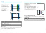
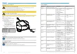
The product has reached its zero position if the
gripper jaws are at the pictured position when
referencing (Homing DeviceMode 10).
Depending on installation size, the gripper
jaws move slightly beyond the edge of the
gripper housing when moving to home position
(Homing).


