5
All information contained herein is the exclusive copyright of Round Bank Engineering Ltd and is not to by copied,
duplicated or otherwise distributed without the express permission of Round Bank Engineering Ltd, Unit 7, Victoria
Business Park, Halifax, UK, HX1 5ND - +44 (0) 1422 647177
–
Connections
Power Supply Connections
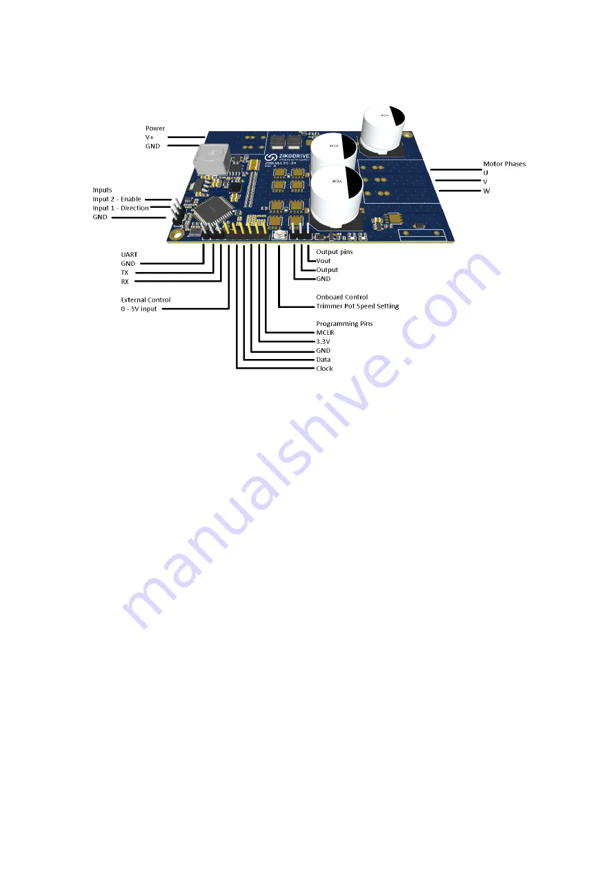
The power supply connections are the clearly marked on the controller and indicated in the drawing
above. Power supply should be between 8-55VDC and you should set an appropriate current limit (if
using a PSU) to enable adequate power. Setting the current limit too low for your motor will result in
impaired performance and potentially will mean the controller will not start.
NOTE: the controller is protected against reverse polarity, however care should be taken to ensure
the polarity is correct before powering the controller.
DO NOT INCREASE THE VOLTAGE WHILE THE MOTOR IS RUNNING, THE BRAKE WILL BE ENABLED
AND WILL CAUSE THE BRAKE TO BECOME DAMAGED.
Motor Connections
Motor connections are on the opposite side of the controller to the power supply inputs. They are
clearly marked on the controller. Take care to match the motor phases with their appropriate
connection. Wiring the motor incorrectly may result in the motor not functioning or the motor
running in the opposite direction to that intended. The motor manufacturer should supply the wire
colour / motor phase information on the motor datasheet.


