background image

 www.scheppach.com / 

 [email protected] / 

 +(49)-08223-4002-99 / 

 +(49)-08223-4002-58

GB | 21 

9.   Attachment  /  Before starting the 

equipment

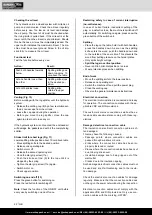
9.1 Fitting the wheels (Fig. 3)

•  Insert the bolt (b) through the wheel (7).
•  Now insert the bolt through the holes in the lower 

part of the splitter.

•  Now secure the bolt with a cotter pin
•  Repeat this process on the other side.

9.2 Fitting the complete control arms (Fig. 4 + 5)

• 

Grease the metal plate

• 

Insert the complete control arm in the position 
provided (Fig. 4).

•  Guide control arm (10) into the rocker switch (7a) 

(Fig. 4)

• 

Secure the complete control arm with a cylindrical 
screw (a), two washers and a self-locking nut.

•  Now fasten the other control arm on the other side 

in accordance with the method described.

•  Attention! Do not clamp the control arms too 

tightly, they must move easily.

• 

Mount­lthe­lsafety­lbars­l(G)­lat­lthe­lend.­lThese­lare­lfitted­l

on the control arm with two Phillips countersunk-
head screws (Fig. 5)

9.3  Installing the claws + additional retainers (Fig. 

6 + 7)

• 

Fasten the additional retainers (D) together with the 
claws (C) on the control arm (Fig. 4)

• 

To do so, insert two hexagon screws (c) through the 
holes on the control arm and secure each with a 
self-locking nut (Fig. 7)

•  Note that the prongs on the claws must point 

towards­leach­lother­lafter­linstallation­l(fig.­l9)

9.4 Installing the table and tray tables (Fig. 8 - 10)

•  Undo the star-grip screw (8a) (Fig. 8)
• 

Now­l fit­l the­l table­l (6)­l in­l the­l retainer­l intended­l (Fig.­l

8) and re-tighten the star grip screws previously 
loosened.

• 

Now hang the tray tables (12) on two screws located 

on­lthe­lside­lof­lthe­ltable­l(6)­lrespectively­l(Fig.­l9­l+­l10)

m

 IMPORTANT!

You must fully assemble the appliance before using it 

for­lthe­lfirst­ltime!

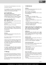
10. Initial operation

Make sure the machine is completely and expertly as-
sembled. Check before every use:
•  The connection cables for any defective spots 

(cracks, cuts etc.).

•  The machine for any possible damage.
• 

The­lfirm­lseat­lof­lall­lbolts.

•  The hydraulic system for leakage.
•  The oil level.

•  Health hazard due to electrical power, with the use 

of improper electrical connection cables.

•  Release the handle button and switch off the ma-

chine prior to any operations.

•  Avoid accidental starts of the machine: Do not press 

the start button while inserting the plug into the socket.

•  Use the tools recommended in this manual to ob-

tain the best results from your machine.

•  Always keep hands away from the work area when 

the machine is running.

7.  Technical data

Motor V/Hz

230V / 50Hz 400V / 50Hz

Input P1 W

3000 W

Output P2 W

2100 W

2250 W

Operating mode

S6 40%

Motor speed 1/min

2800

Dimensions D/W/H

920 x 690 x 1520 mm

Table height 

815 mm

Working height 

900 mm

Log length & 

Ø

550 mm / Ø min. 70 mm, 

max. 400 mm

Power max. tons*

8

Piston stroke 

450 mm

Forward speed 

4 cm/s

4 cm/s

Return speed 

10 cm/s

12  cm/s

Oil quantity 

4 l

Weight 

97 kg

Subject to technical changes!

8.  Unpacking

Open the packaging and remove the device carefully.
Remove the packaging material as well as the pack-
aging and transport bracing (if available).
Check that the delivery is complete.
Check the device and accessory parts for transport 
damage. In case of complaints the dealer must be 
informed immediately. Subsequent complaints will 
not be accepted. If possible, store the packaging until 
the warranty period has expired.
Read the operating manual to make yourself familiar 
with the device prior to using it.
Only use original parts for accessories as well as for 
wearing and spare parts. Spare parts are available 
from your specialized dealer.
Specify our part numbers as well as the type and year 
of construction of the device in your orders.

m

 ATTENTION

The device and packaging materials are not toys! 

Children must not be allowed to play with plas-

tic bags, film and small parts! There is a risk of 

swallowing and suffocation!

Содержание Yellow Gardenline New Generation 400V YPL N.G.

Страница 1: ...ung Technische nderungen vorbehalten Abbildungen beispielhaft DE Holzspalter Original Betriebsanweisung 8 GB Log splitter Translation from the original instruction manual 17 Art Nr 898 33 3905321972 A...

Страница 2: ...www scheppach com service scheppach com 49 08223 4002 99 49 08223 4002 58 2 1 1 1 2 4 5 6 7 8 3...

Страница 3: ...www scheppach com service scheppach com 49 08223 4002 99 49 08223 4002 58 9 10 11 12 14 15 13 2 1 2...

Страница 4: ...www scheppach com service scheppach com 49 08223 4002 99 49 08223 4002 58 4 2 A B C D E G H F I a c b...

Страница 5: ...www scheppach com service scheppach com 49 08223 4002 99 49 08223 4002 58 5 3 4 7 8 5 6 7 b a 11 10 7a G D C D C c 8a...

Страница 6: ...www scheppach com service scheppach com 49 08223 4002 99 49 08223 4002 58 6 9 10 13 11 12 12 11a 9 8...

Страница 7: ...www scheppach com service scheppach com 49 08223 4002 99 49 08223 4002 58...

Страница 8: ...ordnungsgem Alt lsammel stelle vor Ort Es ist verboten Alt l in den Boden abzulassen oder mit Abfall zu vermischen Es ist verboten Schutz und Sicherheitsvorrichtungen zu entfernen oder zu ver ndern Nu...

Страница 9: ...ng 10 3 Lieferumfang 10 4 Bestimmungsgem e Verwendung 10 5 Allgemeine Sicherheitshinweise 11 6 Zus tzliche Sicherheitshinweise 11 7 Technische Daten 12 8 Auspacken 12 9 Aufbau Vor Inbetriebnahme 12 10...

Страница 10: ...en Verehrter Kunde Wir w nschen Ihnen viel Freude und Erfolg beim Ar beiten mit Ihrem neuen Ger t Hinweis Der Hersteller dieses Ger tes haftet nach dem gel tenden Produkthaftungsgesetz nicht f r Sch d...

Страница 11: ...rch das wegschleudernde Werk st ck bei unsachgem er Halterung oder F hrung Gef hrdung durch Strom bei Verwendung nicht ord nungs ge m er Elektroanschlussleitungen Bereichen sind zu beachten Ver nderun...

Страница 12: ...t Abb 5 9 3 Montage Krallen Zusatzhalterungen Abb 6 7 Befestigen Sie die Zusatzhalterungen D zusammen mit den Krallen C am Bedienarm Abb 4 Stecken Sie hierzu zwei Sechskantschrauben c durch die Bohrun...

Страница 13: ...enarm los Schalten Sie das Ger t aus und ziehen den Netz stecker Schlie en Sie die Entl ftungsschraube Allgemeine Wartungshinweise beachten Achtung Die Zacken die an den Krallen angebracht sind m ssen...

Страница 14: ...nen Mindestquer schnitt von 1 5 mm aufweisen Der Netzanschluss wird mit maximal 16 A abgesichert Drehstrommotor 400 V 50 Hz Netzspannung 400 Volt 50 Hz Netzanschluss und Verl ngerungsleitung m ssen 5...

Страница 15: ...Teile einem gebrauchsgem en oder nat rlichen Verschlei unterliegen bzw folgende Teile als Ver brauchsmaterialien ben tigt werden Verschlei teile Spaltkeil Spaltholmf hrungen Hyd raulik l nicht zwinge...

Страница 16: ...Die hydraulische Pumpe springt nicht an Spannung fehlt Pr fen ob die Leitungen Stromversorgung haben Der Thermoschalter des Motors hat sich ausgeschaltet Dem Thermoschalter im Inneren des Motorgeh us...

Страница 17: ...waste oil correctly waste oil collection point on site Do not dump waste oil in the ground or mix it with waste Do not remove or modify protection and safety devices Only the operator is allowed in th...

Страница 18: ...description 19 3 Scope of delivery 19 4 Intended use 19 5 Safety notes 20 6 Additional safety instructions 20 7 Technical data 21 8 Unpacking 21 9 Attachment Before starting the equipment 21 10 Initi...

Страница 19: ...According to the applicable product liability laws the manufacturer of the device does not assume liability for damages to the product or damages caused by the product that occurs due to Improper han...

Страница 20: ...hazards can be minimized by following the safety instructions as well as the instructions in the chapter Authorized use and in the entire operat ing manual The manufacturer will not be liable for any...

Страница 21: ...nnection cables for any defective spots cracks cuts etc The machine for any possible damage The firm seat of all bolts The hydraulic system for leakage The oil level Health hazard due to electrical po...

Страница 22: ...sure that the connection cable does not hang on the power network during the inspection Electrical connection cables must comply with the applicable VDE and DIN provisions Only use con nection cables...

Страница 23: ...es Wear parts splitting wedge guides hydraulic oil split ting wedge Not necessarily included in the scope of delivery The printing of the type designation on the connec tion cable is mandatory For sin...

Страница 24: ...body for the disposal of waste electrical and electronic equip ment or your waste disposal company 15 Disposal and recycling The equipment is supplied in packaging to prevent it from being damaged in...

Страница 25: ...08223 4002 58 25 1 3 4 5 6 7 8 9 10 11 12 13 14 15 16 17 22 20 21 18 19 34 35 23 36 37 38 39 40 31 41 42 43 44 45 46 51 52 54 47 48 53 55 56 56 49 50 57 58 59 60 61 62 1 63 64 65 66 22 67 68 23 69 26...

Страница 26: ...smernicama EZ i normama za artikal RO declar urm toarea conformitate corespunz tor directivelor i normelor UE pentru articolul BG 2014 29 EU 2014 35 EU X 2014 30 EU 2004 22 EC 2014 68 EU 2011 65 EU 89...

Страница 27: ...itnochwirdeineneueGarantiezeitdurchdieseLeistungf rdasGer toderf retwaigeeingebauteErsatzteileinGanggesetzt DiesgiltauchbeiEinsatzeinesVor Ort Services Das betroffene Ger t ist in ges ubertem Zustand...

Страница 28: ...Jahre Zgonc Garantie sind M ngel die nicht auf einen Material oder Herstellungsfehler sondern auf Verschlei unsachgem en Gebrauch oder mangelnde Wartung und Pflege zur ckzuf hren sind Hierbei sind di...

Отзывы: