Wiring Diagram
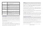
The diagram below shows typical wiring for a complete EVMS installation. Note that the diagram does not show a main fuse (5A recommended) and inertia switch (crash sensor), which should both be
installed between the 12V battery and the EVMS Lite’s 12V supply. You will also usually need to separately use the key signal to switch a relay for powering auxiliary devices such as brake vacuum pump,
power steering pump, water cooling pump, cabin heater, etc. Make sure all wiring has appropriate current and insulation ratings, and that fuses have appropriate DC voltage and current ratings.
EVMS Lite
12
V
G
RO
UN
D
KE
Y
IN
C
H
G
IN
LE
D
BUZZER
D
R
IV
E
AU
XC
TR
C
H
AR
G
E
C
AN
T
ermination
Resistor
1
20
!
B
M
S
12
Battery Box
EVMS: Idle
ZEVA EVMS MONITOR
< SEL >
Fuse
Charger
Main
Contactor
Relay
A
ux
ili
ar
y
C
on
ta
ct
or
B
M
S
12
Battery Box
CAN Termination
Resistor 120!
CAN bus
CAN bus
CAN
b
us
Traction Circuit HV+
Traction Circuit HV-
DC/DC Converter
Motor Controller
B+
From 12V
Battery
Ground
To LED in dash
Charge Door
AC in
Fu
se
B-
To
Motor
D
oo
r S
w
itc
h
A
C
so
ck
et
DC Out
+
–
To 12V
Battery
HV In
+
–
LV Out
+
–
To buzzer in dash
Precharger
From key


