Option Installation
56
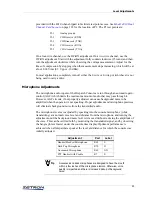
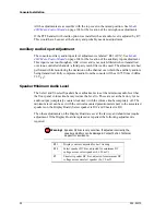
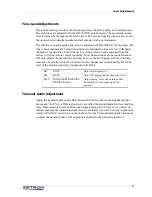
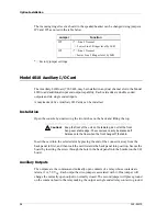
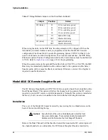
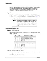
The incoming ringer level as heard in the speaker/headset can be changed using jumpers
JP2 and JP3 as noted in the table below.
* = Factory jumper settings
Model 4010 Auxiliary I/O Card
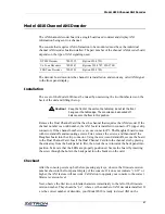
The Auxiliary I/O Board, 702-9448, may be installed in any dual channel slot in the Model
4010 to add additional input and output capability. Each card adds six double ended
outputs and six single ended inputs.
A maximum of five Auxiliary I/O Cards can be installed.
Installation
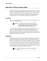
Open the console by unscrewing the two latches on the back and lifting the top.
Insert the card into the selected slot by placing the end of the connector away from the
back panel in first, and then rock the card towards the back panel into position. Secure the
board by inserting the screw through the hole in the back panel into the bracket on the I/O
board.
Auxiliary Outputs
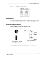
The outputs are the common and normally open contacts of a relay whose contacts are
rated at 1 A, 50 V
DC
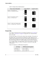
. Each output has two jumpers associated with it. One jumper will
change the normally open output to normally closed. The second jumper will place ground
on the common lead to the relay making the output a single ended relay contact to ground.
Jumper
Function
JP2
+*= Line 2 Normal
- = Lower Line 2 Ringer level by 9dB
JP3
+*= Line 1 Normal
- = Lower Line 1 Ringer level by 9dB
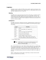
Caution!
Keep the front of the unit on the tabletop; do not let the front
hang over a table edge. The console can easily be knocked off
balance onto the floor when the front hangs off the table.
!
Содержание 4010
Страница 1: ...Model 4010 Radio Dispatch Console Installation and Programming 025 9227S ...
Страница 46: ...Console Installation 46 025 9227S ...
Страница 78: ...Option Installation 78 025 9227S ...
Страница 134: ...Appendix D Troubleshooting 134 025 9227S ...

