background image


18

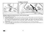
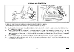
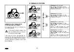
HYDRAULIC SYSTEM 

P+11N014  

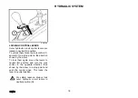
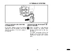
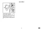
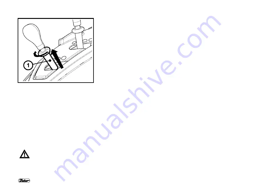
LOCKING CONTROL LEVERS 

Outer hydraulic circuit control levers are 
locked in neutral (N) position. 
To unlock them, raise the lock control (1) 
and turn it to a stop point in the direction 
shown by the arrow. 
To lock them again, move the levers to 
neutral (N) position and turn the lock 
control in the opposite direction than 
shown by the arrow to a stop point and 
push the control down. This locks the 
lever in neutral position. 
 

For safety reasons, always lock 
outer hydraulic circuit levers in 
neutral position (N). 


Содержание Proxima Plus 100

Страница 1: ......

Страница 2: ...th the contents of this manual even though you may be experienced in operating other tractors The manual contains new information and overview of how the tractor may be used in different kinds of work...

Страница 3: ...2 Technical specifications and information on construction equipment material or outer appearance is valid at the moment of printing The manufacturer reserves the right for any change...

Страница 4: ...ear three point hitch 15 Exterior rear hydraulic arms controls 16 Outer hydraulic circuit 16 Outer hydraulic circuit controls 17 Locking control levers 18 Different functions of outer hydraulic circui...

Страница 5: ...4 PROXIMA PLUS TRACTORS TRACTORS WITH FRONT DRIVE AXLE 4WD Tractor Type Engine Power kW Z90 60 Z100 66 Z110 74 G1...

Страница 6: ...it down after it is unlocked by mov ing the lever 1 in the direction shown by the arrow After adjusting lock the wheel by pressing the lever 1 in the opposite direction than shown by the arrow Adjust...

Страница 7: ...PTO shaft switch 2 front shaft switch 3 two position switch of the windscreen wiper and washer 4 rear window wiper switch 5 switch of front working lights on cab roof 6 switch of rear working lights o...

Страница 8: ...uid coolant If the glow plug indicator does not illuminate but flashes there is an error of the ignition system Igni tion system error signals chap ter Have the error repaired in a specialized service...

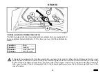
Страница 9: ...8 AGRICULTURE MACHINERY DRIVE E358 MAXIMUM TRANSFERED POWER Shaft Transferred Power front 1000 min 1 60 kW rear 1000 min 1 full engine output 540 min 1 full engine output 540E min 1 full engine output...

Страница 10: ...rce of pressure oil Oil is taken from reservoir shared by gearbox and transmission Hydraulic pump cannot be switched off If the engine is working the pump is on The amount supplied is 50 liters per mi...

Страница 11: ...e lifting of the rear three point hitch Position regulation img 1 the tool connected to the rear three point hitch is auto matically kept in the same height position with regard to the tractor Mixed r...

Страница 12: ...p FREE FLOATING POSITION Free floating position makes it possible to work with tools with a support wheel In this position the arms of the rear three point hitch are loose Move lever 2 to the front po...

Страница 13: ...f the arms of the rear three point hitch turning it in a direction increases the speed If the knob is turned in b direction to its stop point the arms of the rear three point hitch cannot be lowered H...

Страница 14: ...t tools which are connected to the rear three point hitch always use position regulation To raise tools into transport position turn the three point hitch lowering speed control knob 3 in the directio...

Страница 15: ...to the adjustable stop 5 Move lever 1 to g position accelerate the tractor and move lever 1 in the direction shown by the arrow to set the depth of till ing in g position depth is the lowest Once the...

Страница 16: ...resistance Set the depth of tilling by lever 1 as described in Power regulation of the lifting of the rear three point hitch Then start moving lever 2 in the direction shown by the arrow until the arm...

Страница 17: ...n shown by the arrows moving the lever is restricted with a link By repeating this procedure hydraulic arms are lowered in small steps Raising hydraulic arms img C Move lever 3 in the direction shown...

Страница 18: ...the following combinations of control levers and quick couplers can be supplied lever a quick couplers 1 and 2 levers a and b quick couplers 1 2 3 and 4 levers a b and c quick couplers 1 2 3 4 5 and...

Страница 19: ...and turn it to a stop point in the direction shown by the arrow To lock them again move the levers to neutral N position and turn the lock control in the opposite direction than shown by the arrow to...

Страница 20: ...ver a is locked in this position In case pressure exceeds 16 5 MPa when connected to quick coupler 1 lever a automatically returns to N position kick out function 2 Pressure in quick coupler 2 Quick c...

Страница 21: ...is necessary to hold lever b in this position when released lever b automatically returns to N position In addition quick coupler 3 is equipped with a one way valve convenient for connecting a tool w...

Страница 22: ...ed with the drain It is necessary to hold lever c in this position when released lever c automatically returns to N position In addition quick coupler 5 is equipped with a one way valve convenient for...

Страница 23: ...flat terrain Max amount of oil taken 20 liters Gearbox filling standard filling within the range shown by lines A Working area in a slope Max amount of oil taken 13 liters Gearbox filling standard fil...

Страница 24: ...led Check the reservoir regularly if it is full empty it ecologically CONNECTING AND DISCONNECTING QUICK COUPLERS When connecting or disconnecting quick couplers be careful about leakage oil which res...

Страница 25: ...out function from overload This function stops the hydraulic engine if pressure in the filling arm exceeds 17 MPa Connecting reverse rotary hydraulic engine Due to its function reverse rotary hydraul...

Страница 26: ...not to be used If the tractor is equipped with front three point hitch use lever b to control it When the front three point hitch is used quick couplers cannot be connected as they are pressured toget...

Страница 27: ...er supply 4 15A high beam headlamps and indicator 5 15A side lamps dashboard lamps license plate lamps 6 15A right side lamps rear working lamp and indicator 7 15A right low beam headlamps fog lamps a...

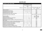
Страница 28: ...ing coolant every other year Changing brake fluid every other year Changing oil in gearbox and transmission o 1500 Changing oil in rear axle portals o 1500 Changing insertion piece of gearbox oil clea...

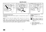
Страница 29: ...and remove the filter 5 To place a new filter proceed contrariwise Put the oil which has flown out back to gearbox this holds if it is necessary to change the filter outside the period recommended for...

Страница 30: ...E751 STRETCHING THE V BELT If the V belt is stretched correctly the belt flexure must be 5 5 mm when apply ing 25 N pressure on one belt Stretch the V belt as recommended after loosening alternator fa...

Страница 31: ...ower drawbars of the rear thee point hitch during the entire lift while using up the maximum pressure with 2 outer cylinders cylinder 75mm in diameter kN 38 Lift capacity at the end of the lower drawb...

Страница 32: ...floating position 11 Fuse box 26 H Hitches 25 Hydraulic system 9 Hydraulic system sensitivity control 12 Hydraulics control panel 10 CH Changing suction filter 28 Chaning fillings and filters 27 Chan...

Страница 33: ...Supllement Operator s manual Proxima Plus 90 Proxima Plus 100 Proxima Plus 110 Edition 1 100 2011 Publication No 222 212 580 Zetor Tractors a s Department of Technical Documentation Trnkova 111 632 0...

Страница 34: ......

Отзывы: