


A
Lower draw bar with CBM hooks
65
Lower draw bar with slipping out end pieces
65
Accumulator battery
75
Accumulator battery maintenance
76
Acquaintance with the tractor
25
Adjusting clutch pedal
98
Adjustment
97
Adjustment of toe-in of the wheels of the front driving axle
68
After starting the engine
79
After wirk with front implements and in case of cooler
clogging
22
Aggregation with trailer and semitrailer
51
Air condition maintenance
95
Air Filter Maintenance
88
Air system tightness inspection
94
Air-condition filtration elements
95
Alternator
76
Alternator maintenance
76
Anti-freezing solution for filling tires
73
Automatic mouth of the CBM stage hitch
50
Auxiliary hydraulic switchboard control
32
B
Ballast weights
71
Ballast weights in front of bonnet grill
71
Basic service information
75
Battery disconnector
34
Battery disconnector
75
Bearing capacity of rear tires
101
Before starting the engine
79
Before you start the engine
37
Bleeding the Heating System
91
Bottom rear window
26
C
Cab air condition
30
Cab heating
29
Cab heating registers
29
Cartridge Replacement in the Fine Fuel Filter
87
Cartridge Replacement in the Raw Fuel Filter
87
Clearance-circle and turning circle diameter
102
Connecting and disconnecting quick couplings of trailer
hydraulic brakes
44
Connecting machines and tools to External hydraulic circuit
62
Coolant replacement
92
Cooling system
21
D
Dashboard
30
Detaching tractor
96
Differential lock
32
Differential lock
42
Direction indicator switch
28
Draining liquid from tires procedure
72
Draining oil from engine
85
Draining the condensate from air collector
95
Drive away
39
Drive of agricultural machinery
53
Drive of machines with greater inertia masses
56
Driver´s seat
27
Driving operation
12
Driving operation
37
Driving with front drive axle engaged
42
E
Electric installation
75
Engine heating
38
Engine oil level
21
Engine Performance Limitation
39
External hydraulic circuit
60
Extrernal hydraulic circuit control elements
60
F
Filling tires with liquid procedure
72
Filling, controlling and draining hole of oil of front drive axle
94
Filling, controlling and draining hole of oil of front wheels
reducers
94
Filtration elements cleaning
95
Fire prevention principles
13
Fixed and free position of lower hydraulic draw bars
64
Flat belt drive tension of accessories
97
Foot brakes pedals
42
Free (floating) position
58
From 100 hours of operation
47
Front bonnet opening
85
Front drive axle control
42
Front drive axle control lever
34
Front drive axle fenders
68
Front hook
49
Front passenger´s seat notification
15
Front tires steerability
100
Front wheels toe-in
68
Front windshield wiper and washer
28
Fuel
82
Fuel Filtering
86
Fuel system leaks
21
Fuel system venting
88
Fuel tank
35
Fuse box
77
G
Gear shifting
40
Gear shifting from higher to lower gears
41
Gear shifting from lower to higher gears
41
Gear shifting lever
33
Gear system drain plug
93
General principles of new tractor run-in in first 100 hours of
operation
47
General safety regulations
11
H
Headlights switch
28
Heating filtration element
94
Hinged lid
26
Hitches
22
Hitches
63
Hydraulic brakes of trailers
44
Hydraulic control
32
Hydraulic control panel
57
Hydraulic equipment
57
Hydraulic sensitivity system control
58
Hydraulic system
57
Hydraulic system
101
Hydrostatic steering
22
Hydrostatic steering failure warning signalization
45
CH
Change of front wheels track with front drive axle
67
Checking amount of oil in hydrostatic steering tank
89
Checking oil levels in engine
85
Checking the oil in gear box, final drive housing and rear
axle
92
I
If engine does not start
38
Immediately after start
38
Important notification
45
In first 10 hours of operation
47
Independent PTO shaft revolutions
102
Information Display - Basic View
31
Information Display - Fault Notifications
31
Information Display - Maintenance Notifications
31
Internal hydraulic circuit control elements
57
L
Leaving the tractor
45
Lights adjustment in cab roof check
78
Lights adjustment in tractor´s grill
78
Lights adjustment in tractor´s grill check
78
Limiting draw bars
64
Liquid for the cooling system of the tractors
82
Location of serial numbers
9
M
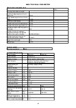
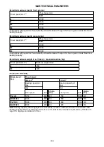
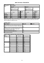
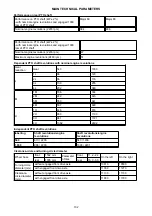
Main technical parameters
99
Main tractor's parameters (mm)
99
Maintenance and treatment of tires
96
Maintenance instructions
85
Making front wheels stable
71
Manipulation with starter
38
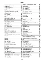
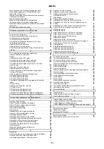
INDEX
103
Содержание MAJOR
Страница 1: ...60 80 Tractor is Zetor Since 1946 OPERATOR S MANUAL MAJOR 01 2014...
Страница 3: ...2...
Страница 8: ...Clearance circle and turning circle diameter 102 Index 103 CONTENTS 7...
Страница 9: ...NOTES 8...
Страница 21: ...NOTES 20...
Страница 25: ...NOTES 24...
Страница 37: ...NOTES 36...
Страница 47: ...NOTES 46...
Страница 49: ...NOTES 48...
Страница 53: ...NOTES 52...
Страница 67: ...NOTES 66...
Страница 71: ...NOTES 70...
Страница 75: ...NOTES 74...
Страница 85: ...NOTES 84...
Страница 106: ...NOTES 105...
Страница 108: ...Made in EU www zetor com zetor zetor com...