Removal of Triac Boards
6 . Unscrew the Triac connectors on the boards to be replaced from the left-hand side of the unit.
7 . Working through each individual channel to be replaced, cut the cable ties on the Live and Load wires. Disconnect
each wire, untangle any wires that are twisted together (as you may need the length later) and mark up where the wire
came from.
8 . Disconnect the ribbon cable(s) attached to the Triac Board and remove the PCB by unscrewing the 3 screws. Slide
the board away from the Triacs then lift out.
9 . Lift the Triac Clip and slide out the Triac. With the Triac removed the clip is no longer tensioned and can be
removed.
Fitting Relay Cards
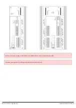
10 . Relay cards are to be assembled to the left-hand side of the enclosure only.
If a relay card is to be assembled at the middle position, then the thermal sensor is required.
If a relay card is to be assembled to the top or bottom position, then the thermal sensor must be removed from
the board by cutting its pins.
11 . Slide the Relay Board into position ensuring the side of the PCB is located in the retaining slot and insert the
screws but do not fully tighten.
12 . Apply pressure to the (screw) side of the PCB to ensure that it is fully located in the slot and while maintaining the
pressure, tighten the screws (if you don’t do this it can pop out of the slot when you are pushing the connectors on).
13 . If the central board has been replaced, then you must fit the Triac clip to the thermal sensor.
14 . Fit the coil wires first, running them around each side of the relay, then the Live and Load wires. Note: The coil
connections are not electrically connected to the circuit, they are physically connected to the PCB, and are there to
secure the wires only.
15 . Fit the DC supply cable to the furthest/lowest board closest to the PCB and use the link wires to connect theothers.
Reassembly
16 . Refit all covers, reusing the screws that have been retained.
Zero 88 - Chilli Pro - Page 55 of 60
Printed: 23/03/2021 09:13:40 ES


