Zephyr ZGS-12000-1 Скачать руководство пользователя страница 14


ZOM-12000-1 rev 0 


Page14 of 15 


Содержание ZGS-12000-1

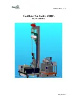
Страница 1: ...ZOM 12000 1 rev 0 Page1 of 15 Fixed Hoist Test Facility FHTF ZGS 12000 1 ...

Страница 2: ...cture is equipped with a chain hoist to raise the UUT up to the top of the structure where it is attached to two load cells The two load cells provide signals to a load cell summing box where the signals are summed and sent to a display The load readout can be set to zero to tare the readout with no load applied to the rescue hoist hook The wire rope tensile load is provided by the MGSE The MGSE p...

Страница 3: ...set the hoist s limit switches adjust the levelwind adjust the flow control and replace and season the wire rope before the UUT is mounted onto the aircraft thus minimizing aircraft down time and flight time required if those procedures were carried out on the aircraft System Picture Installation Requirements The hydraulic supply must be blocked to sit firmly on the Upright assembly base The locat...

Страница 4: ...on should be located so that when the system is being used personnel who are using it can not be injured from other activities in the hanger that they will not be aware of because of their focus on the UUT and MHGSE System Floor Plan Figure 2 ...

Страница 5: ...the hand control raise the hanging hoist mount up to reattach the two clevis pins then lower the chain hoist to apply all the weight to the load cells Attach the hydraulic adapter fittings to the input block as shown in figure 4 The input or pressure line is the 6 fitting and the return or tank line is the 8 fitting Attach the UUT electrical cable ZGS 12128 1 to the J1 connector The J2 connector i...

Страница 6: ...ZOM 12000 1 rev 0 Page6 of 15 Figure 6 Check to insure all lines and fittings are secure and the area is clear ...

Страница 7: ... the rear of the hydraulic power supply as shown in Figure 7 The pressure on and off switch and the indicator switches are as shown in Figure 8 Pressure On Flow Delta Press Indicator switch Load Indicator switch Figure 8 Wire Rope Load Indicator Panel Display Flow Indicator Panel Display Delta Pressure Indicator Panel Display Start ...

Страница 8: ...te the pressurized hydraulic reservoir of the aircraft Pressure transducers mounted in the pressure and return lines provide signals to the delta pressure indicator The hydraulic tank item 1 has a 20 gallon capacity and uses MIL H 83282 hydraulic fluid System Startup Procedure With the hydraulic lines installed and all fittings tightened turn on the hydraulic supply drive motor by pressing the sta...

Страница 9: ... system The system is not equipped with QD fittings due to the possibility of the QD on the return line not being seated and the hydraulic heat exchanger on the UUT being damaged The guide track on the upright beam should be lubricated with white lithium grease as required to insure low friction at the hanging hoist mount interface Electrical Schematics ZGS 12132 1 Junction Box Schematic ZGS 12135...

Страница 10: ...ZOM 12000 1 rev 0 Page10 of 15 Assembly Drawing and major parts list ZGS 12000 1 ...

Страница 11: ...ZOM 12000 1 rev 0 Page11 of 15 ...

Страница 12: ...ZOM 12000 1 rev 0 Page12 of 15 ...

Страница 13: ...ZOM 12000 1 rev 0 Page13 of 15 ...

Страница 14: ...ZOM 12000 1 rev 0 Page14 of 15 ...

Страница 15: ...ZOM 12000 1 rev 0 Page15 of 15 ...

Отзывы: