

Technical Documentation
© Zennio Avance y Tecnología S.L. Edition 1 Further information
www.zennio.com
Page
2
/
2
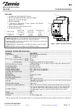
INPUTS: SPECIFICATIONS AND CONNECTIONS
BATTERY REPLACEMENT
SAFETY INSTRUCTIONS
Do not connect Mains Voltage (230 V) or any other external voltages to any point of the BUS. Connecting an external
voltage might put the entire KNX system at
risk.
Make sure during the installation that there is always sufficient insulation between the mains voltage 230V and the bus or
the extension inputs.
Once the device is installed, the terminals should not be accessible.
Concept
Description
Number of S0 or dry inputs
4
Minimum pulse length
30ms
Inputs connection
Terminal block (screw)
Inputs per common
2
Recommended cable section 0.25 mm² to 2.5 mm²
Max. cable length
30m
Cable type
Stranded or solid wire
Operating voltage
6VDC
1.
Extract the battery holder from the upper
side of KCI. It is recommended to have the
bus KNX connected during this process to
prevent S0 pulses loss.
2.
Place the batteries in the battery holder (respecting the polarity
shown) and insert it as indicated in the figure.
Figure 2:
Example of connections with SO pulse generators