Zenmuse H3-3D Gimbal Скачать руководство пользователя страница 17

©2014  DJI  Innovations.  All  Rights  Reserved.                                                                                                                                       

17 

4 Test Fly 

4.1 Check List Before Flight 

For safety reasons, check of the following items before each flight: 

(1)


Gimbal  is  firmly  installed  to  aircraft,  and  camera  mounted  correctly.  Make  sure  the  camera  is  aligned 

parallel with nose direction of the aircraft.   

(2)


All cables are firmly and correctly connected.   

(3)


Ensure gimbal video signal cable is in solid soldering condition.   

(4)


Make sure the wi

reless

 video transmission module is connected to GCU before powering on the system.


(5)


Transmitter is properly configured.   

(6)


Camera connection is correct. 

(7)


GCU and flight control system connection is correct.   

(8)


Flight control firmware version is latest.   


4.2 Gimbal Test 


1.


Ensure all the batteries are fully charged. 

2.


Switch on the transmitter. 

3.


Power on the camera first then power on the gimbal and wait until gimbal self-test completes. 

4.


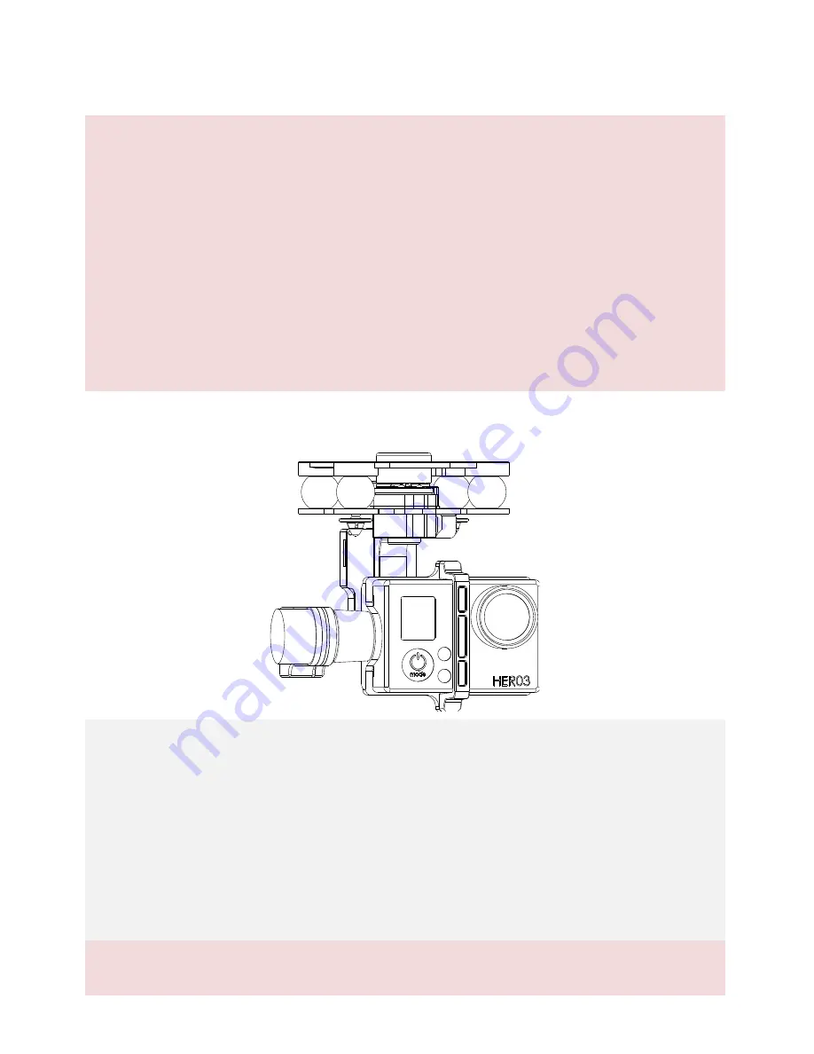
Initialization  completes,  camera  lens  point  to  aircraft  nose  direction,  that  is,  the  three  axes  of  gimbal 

should be in the condition as the above diagram shows. 

5.


Toggle the tilt control switch on your transmitter, and make sure it is working properly. Then try to feel if 

your gimbal moves to the corresponding direction. If not, check your settings. 

6.


When finishing test, power off the gimbal first then the camera. 

Note: 


If the gimbal is not working normally, refer to 

Trouble Shooting for solutions. 

Содержание H3-3D Gimbal

Страница 1: ...2014 DJI Innovations All Rights Reserved ZENMUSE H3 3D Gimbal User Manual V1 02 2014 06 09 www dji com...

Страница 2: ...manual to mount and connect gimbal on your aircraft User of this product shall respect the AMA s National Model Aircraft Safety Code DJI Innovations has no control over use setup final assembly modif...

Страница 3: ...greatly reduce the vibrations Gimbal Controller Unit GCU 1 Connect gimbal controller to flight control system using CAN Bus Power GCU and gimbal through 3S 6S power cable 3 Accessory Pack 1 The acces...

Страница 4: ...ontroller unit and your wireless video transmission module connection transmitting the video signal Accessory Pack CAN Bus Cable 1 Use CAN Bus to connect the GCU with the flight control system DJI DJI...

Страница 5: ...4 FINAL CHECKS 9 2 GCU CONNECTION 10 2 1 CONNECT GCU AND FLIGHT CONTROL SYSTEM 10 2 2 VIDEO CONNECTION 14 3 CONFIGURATION 15 3 1 DRIVER AND ASSISTANT SOFTWARE INSTALLATION 15 3 2 ASSISTANT SOFTWARE GU...

Страница 6: ...he obstacles at once if the operating gimbal is being blocked 3 Always mount camera before powering on the gimbal 1 1 1 Rear View 1 1 1 2 1 3 1 4 1 6 1 7 1 8 1 5 1 Yaw servo driver module 2 Upper plat...

Страница 7: ...pins through the holes on the highlighted diagonal position shown below Then attach and secure the upper plate of damping unit to the Phantom 2 with four M3x5 screws 2 Attach the damping unit bottom...

Страница 8: ...board with the 8 pin port on the gimbal via the supplied 8 pin cable Caution 1 Aircraft and accessories are not included with gimbal 2 Camera must be aligned with the nose of the aircraft 3 Gimbal is...

Страница 9: ...al before you proceed to mount the GoPro camera to the H3 3D gimbal 2 Ribbon cable is a delicate item treat with extreme care Always check the connection per each flight and ensure the ribbon cable co...

Страница 10: ...to the flight control system before it is powered on 3 Be sure to mount the camera onto the gimbal before power on the aircraft and the gimbal Otherwise it might damage the servo due to the incorrect...

Страница 11: ...n Connect to the CAN 2 port on the A2 Connect the GPS Compass module to spare CAN Bus port on PMU Connect the GPS Compass module to the GPS port of PMU V2 Refer to 2 2 GCU and DJI flight control Syste...

Страница 12: ...roller is correct Refer to the Gimbal Assistant Software for details 2 2 GCU and Flight Control System Connection positive pole negative pole Battery 3S 6S Note The GCU can be connected to any CAN por...

Страница 13: ...Connection Diagram Leave as is To Battery Note The PMU and GCU can both connect to the same battery Gimbal Tilt Control Control the tilt motion via X1 channel Properly configure the corresponding chan...

Страница 14: ...ed to use standard gimbal video signal cable Make sure you solder the gimbal video signal cable to the wireless video transmission module firmly Insulated all the cables to prevent short circuiting Le...

Страница 15: ...finish installation 4 Run the Assistant Software 3 2 Assistant Software GUI Connect GCU to the PC via a Micro USB cable and then power on the GCU Communication indicator Blue LED On Lost communication...

Страница 16: ...irmware upgrade completes 10 Click OK and power cycle the system to finish the upgrade process Notes 2 CMU stands for Camera Multi Unit which is management module for the camera 3 To eliminate the int...

Страница 17: ...ect 7 GCU and flight control system connection is correct 8 Flight control firmware version is latest 4 2 Gimbal Test 1 Ensure all the batteries are fully charged 2 Switch on the transmitter 3 Power o...

Страница 18: ...e battery pack to test the gimbal at the beginning to ensure functionality before making steps to power on of flight controller gimbal OSD FPV gears etc Appendix Trouble Shooting NO Symptom Cause Acti...

Страница 19: ...2014 DJI Innovations All Rights Reserved 19...

Страница 20: ...tant Software System Requirement Windows XP SP3 Windows 7 Windows 8 Mechanical Electrical Characteristics Working Current Static current 400mA 12V Dynamic current 600mA 12V Gimbal Input Power 3S 6S 12...

Отзывы: