P A G E 1 5
206-3594
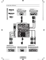
TV back
C
R
C
B
Y
R
L
P
R
P
B
Y
R
L
R
L
R
L
R
L
COMPUTER
INPUT
VIDEO 2
IN
VIDEO 1
IN
DVD IN
HD IN
OUTPUT
AUDIO
AUDIO
AUDIO
AUDIO
AUDIO
MONO
MONO
HD/COMPUTER
VIDEO
VIDEO
VIDEO
S-VIDEO 1
S-VIDEO 2
G-LINK
Typical
Telephone
Line
Output
Jack
LINE IN
TO
PHONE
Connect a standard tele-
phone line cord between the
telephone output jack and
the LINE IN jack on the TV
back connections panel.
Connect your telephone to
the PHONE jack on the TV
back connections panel.
Notes: Caller ID service is
available from your local
telephone service provider.
Telephone line cords shown
are not included with TV.
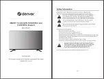
Caller ID / GUIDE Plus+ Connections
Caller ID Hookup
GUIDE Plus+ Hookup
Locate the jack marked G-LINK.
This jack is for the IR Cord
connection. Insert the connec-
tor into the G-LINK jack.
Place the other end of the
cords with the IR emitter send-
ing units in front of your VCR
and Cable Box in such a way as
to allow for an unrestricted
path for the IR signals to be
able to reach the front panels
of the VCR and Cable Box.
IR=Infrared
Note: See page 21 and 48 for
GUIDE Plus+ feature informa-
tion and setup.
TV back
P
r
P
b
Y
R
L
P
r
P
b
Y
R
L
R
L
R
L
R
L
RGB/
COMPUTER
INPUT
VIDEO 2
IN
VIDEO 1
IN
DVD IN
HD IN
MONITOR
OUTPUT
AUDIO
AUDIO
AUDIO
AUDIO
AUDIO
MONO
MONO
HD/COMPUTER
VIDEO
VIDEO
VIDEO
S-VIDEO 1
S-VIDEO 2
G-LINK
VCR
Cable Box
17
LINE IN
TO
PHONE
Connect your telephone to your Entertainment Machine and
use your local phone service provider’s Caller ID feature
Use your Entertainment Machine to control your cable box and VCR with the GUIDE Plus+ feature