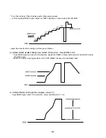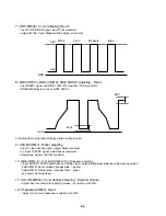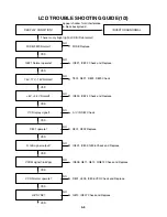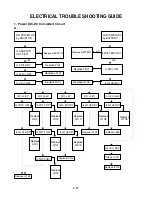
1-4
Fig. 3
SAFETY CHECK AFTER SERVICING
Examine the area surrounding the repaired location for damage or deterioration. Observe that screws, parts and
wires have been returned to original positions. Afterwards, perform the following tests and confirm the specified
values in order to verify compliance with safety standards.
• Insulation resistance test
confirm the specified insulation resistance or greater between power cord plug prongs and externally exposed
parts of the set (RF terminals, antenna terminals, video and audio input and output terminals, incrophone jacks,
earphone jacks, etc.) See table below.
• Dielectric strength test
Confirm specified dielectric strength or greater between power cord prongs and exposed accessible parts of
the set (RF terminals, antenna terminals, video and
audio input and output terminals, incrophone jacks,
earphone jacks, etc.) See table below.
• Clearance distance
When replacing primary circuit components, confirm
specified clearance distance (d), (d') between sol-
dered terminals, and between terminals and sur-
rounding metallic parts. See table below.
Table 1 : Ratings for selected areas
* Class II model only.
Note. This table is unofficial and for reference only. Be sure to confirm the precise values for your particular
country and locality.
• Leakage Current test
Confirm specified or lower leakage current between B(earth ground, power cord plug prongs) and externally
exposed accessible parts (RF terminals, antenna terminals, video and audio input and output terminals, micro-
phone jacks, earphone jacks, etc.)
Measuring Method: (Power ON)
Insert load Z between B(earth ground, power cord
plug prongs) and exposed accessible parts. Use an
AC voltmeter to measure across both terminals of
load Z. See figure and following table.
Table 2:Leakage current ratings for selected areas.
Note. This table is for IEC member only. Be sure to confirm the precise values for your particular country and
Note.
locality.
Chassis
d
a
Primary circuit terminals
Exposed
accessible
part
Z
Load
AC Voltmeter
Earth Ground,
Power cord plug prongs
B
Fig. 2
AC Line Voltage
AC Line Voltage
100 to 130 V
200 to 240 V
*100 to 130 V
*
200 to 240 V
Europe
Australia
Europe
Australia
Other terminals
Antenna earth
terminals
i
E
0.7m A peak
i
E
2m A DC
i
E
0.7m A peak
i
E
2m A DC
F
10 M
Ω
/500 V DC
4kV 1 minute
F
6mm(d)
F
8mm(d)
(a Power cord)
Region
Load Z
Leakage Current(i)
Earth Ground
(B) to :
Region
Insulation
Resistance
Dielectric
Strength
Clearance
Distance(d),(d)
2k
Ω
50k
Ω
Содержание DVP7771
Страница 8: ...2 3 Deck Mechanism Section 430 430 001 430 002 002 006 005 004 003 002 431 431 007...
Страница 32: ...MEMO...
Страница 37: ...3 15 3 16 LCD P C BOARD LOCATION GUIDE LOCATION GUIDE...
Страница 38: ...MEMO MEMO...
Страница 44: ...3 42 3 43 6 PANTER CIRCUIT DIAGRAM waveforms page 3 58 3 59 2002 02 01 R14113A...
Страница 45: ...3 44 3 45 7 MEMORY CIRCUIT DIAGRAM 2002 02 01 R14114A...
Страница 46: ...3 46 3 47 8 X BUS CIRCUIT DIAGRAM Q501 is defective Key S W voltage abnormal 2002 02 01 R14115A...
Страница 47: ...3 48 3 49 9 CPLD CIRCUIT DIAGRAM 2002 02 01 R14116A...
Страница 51: ...3 56 3 57 13 REMOCON CIRCUIT DIAGRAM Remocon not operate Q902 is defective LED not operate 2002 02 01 R14123A...
Страница 54: ...3 62 3 63 PRINTED CIRCUIT DIAGRAMS 1 MAIN P C BOARD LOCATION GUIDE LOCATION GUIDE...
Страница 55: ...3 64 3 65 2 FRONT KEY P C BOARD LOCATION GUIDE LOCATION GUIDE...
Страница 56: ...MEMO MEMO...


