Carl Zeiss
Left Tool Area and Hardware Control Tools
Lightsheet Z.1
176
000000-1790-528
02/2013
The activated (blue)
Automatic
button loads the
settings which have been previously defined with
the Automatic Detector Alignment for each light
path.
After pressing the
Continuous
button in the
Manual Detector Alignment
window or in the
Main tool tabs
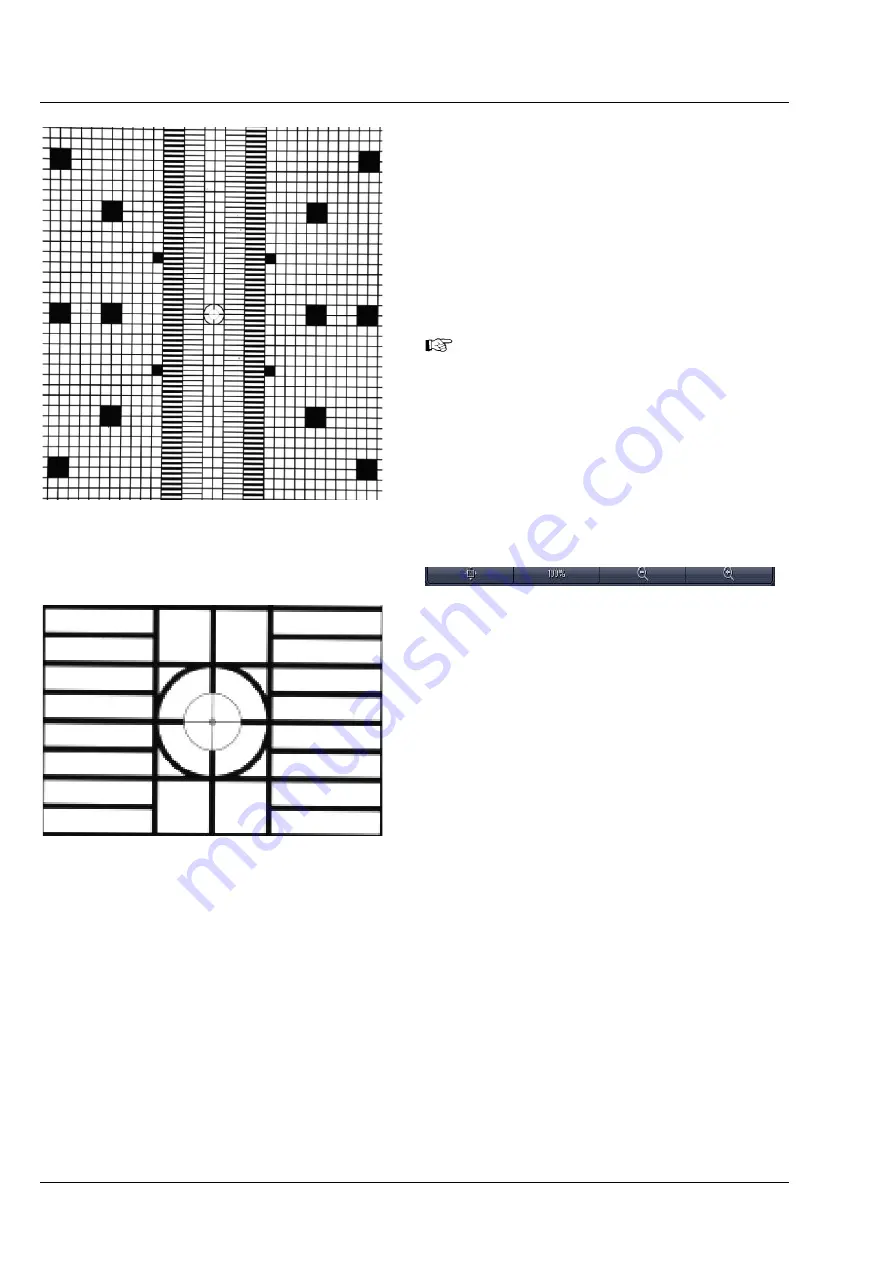
, a new image will open with a live
image of the grating (Fig. 273).
When the grating is out-of-focus, refocus it
for the relevant channel by performing the
steps described in
CHAPTER 1 HARDWARE
.
To check the focus, zoom into the image
using the
Zoom
function and look at the
center cross within the square (Fig. 274). If
the white portions within the inner square
are recognizable, the grating is in focus.
To zoom into the image, use these buttons:
As a reference, the combination of Emission
Selection filter position 1 and Cam 1 should be
taken (see above), so this combination should give
the first live image. Here mark a structure close to
the middle with a cross using the
Graphics View
control
. This cross will now be the reference for
the following steps.
Now change the light path to the combination of
Emission Selection filter and Channel (Cam 1 or
Cam 2) that you wish to adjust. The live image will
now show the grating with the current settings.
Use the sliders or the input box with arrows of
Cam 1 X
and
Cam 1 Y
(for Channel 1, Cam1) or
Cam 2 X
and
Cam 2 Y
(for Channel 2, Cam 2) to
move the previously chosen structure of the
grating to overlay with the cross. Finish this step by
pressing the
Store Current Settings
button.
Repeat the procedure for all desired Emission
Selection filters and channels, always using the
drawn cross marker as the reference.
Fig. 273
Manual Detector Alignment, Grating at
Zoom 1
Fig. 274
Manual Detector Alignment, Grating,
center part zoomed in
Содержание Lightsheet Z.1
Страница 1: ...Lightsheet Z 1 Operating Manual February 2013 ZEN 2012 black edition ...
Страница 4: ......
Страница 170: ......
Страница 427: ...Lightsheet Z 1 Overview ...


