background image

   63 - NL

4.4 Aansluiting van het vloeistofcircuit 

(aardwarmtecollector)

 De ComfoFond-L Eco maakt gebruik van een 
aardwarmtecollector die aardwarmte aan de grond 
onttrekt en aan de lucht die door de ComfoFond-L 
Eco stroomt afgeeft. De aardwarmtecollector wordt 
gevormd door een PE buis. De lengte van de buis is 
afhankelijk van de locale omstandigheden, zoals het 
type grond en het grondwaterniveau. Vaste grond 
bevat meer energie dan losse grond. Als de buis 
onder het grondwaterniveau ligt, dan kan er veel 
energie aan de bodem ontrokken worden. 
 De buis dient min of meer horizontaal in de bodem 
gelegd te worden op een ideale diepte van 1,2 tot 1,6 
meter. 
 
 Bij de berekening van de lengte van de buis 
dient alleen de lengte die feitelijk in de grond ligt 
meegerekend te worden. De lengte binnenshuis heeft 
verder geen invloed op de energie die het systeem 
kan onttrekken. In zandgrond dient er met een 
dubbele buislengte rekening gehouden te worden.

  Bij de specificaties van de ComfoFond-L Eco is 

terug te vinden welke lengte buis het beste kan 
worden gebruikt. Speciale software voor het 
uitrekenen van de benodigde buis lengte is te 
verkrijgen bij Zehnder.

 De buis kan in elke willekeurige vorm gelegd worden. 
 Isoleer binnenshuis alle vloeistofleidingen van het 
vloeistofcircuit. Hiermee wordt condensvorming aan 
de buitenzijde van de vloeistofleiding voorkomen. 
Leg de buis bij voorkeur in de grond om het huis 
en houd de lengte binnenshuis zo kort mogelijk. 
Aangeraden wordt om een minimale afstand van 
60 cm aan te houden tussen eventuele lussen 
in de buis, om zo de efficiency te verhogen. Om 
waterleidingen te beschermen tegen bevriezing moet 
de buis minimaal 1 meter verwijderd zijn van de 
aanwezige waterleidingen in de grond.

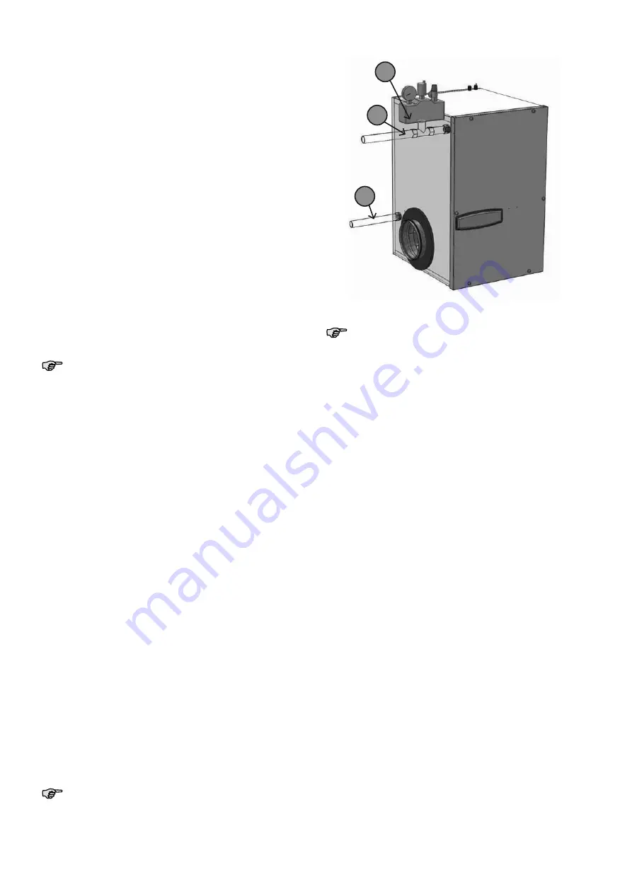
 Monteer de boilerveiligheidsgroep (C) met behulp 
van een T-stuk aan het vloeistofcircuit. Plaats de 
boilerveiligheidsgroep op het hoogste punt van 
het vloeistofcircuit, na bij de afvoerzijde van de  
ComfoFond-L Eco. 
Sluit het ene eind van de PE buis met behulp van een 
verloopstuk aan op vloeistofaansluiting ingang (A) 
van de ComfoFond-L Eco. 
 Sluit het andere eind van de PE buis met behulp van 
een verloopstuk aan op vloeistofaansluiting uitgang 
(B) van de ComfoFond-L Eco.

  De aansluiting van de boilerveiligheidsgroep 

is 1“ binnendraad en de aansluitingen van de 
ComfoFond-L Eco zijn ¾“ rechte buitendraad.

A

B

C

  Achterin deze handleiding bevindt zich een 

installatierapport waarop de gegevens van het 
aangelegde vloeistofcircuit kunnen worden 
genoteerd.

4.5   Elektrische  aansluitingen

 De ComfoFond-L Eco wordt bestuurd en gevoed 
door het ventilatietoestel. Hiervoor moet de 
temperatuursensor en vloeistofpomp van de 
ComfoFond-L Eco worden aangesloten op de 
connectieprint van dhet ventilatietoestel. Deze 
connectieprint zit aan de bovenzijde van het 
ventilatietoestel.

 De temperatuursensor moet worden aangesloten op 
de klemmen die gemarkeerd zijn met de tekst Tge en 
GND. De sensor is niet richtinggevoelig. Het maakt 
daarom niet uit welke kleur draad op de Tge of GND 
klem worden aangesloten.

 De vloeistofpomp moet worden aangesloten op het 
voedingsblok van de connectieprint. Aangezien de 
pomp van de ComfoFond-L Eco niet continu hoeft 
te draaien wordt deze aangesloten op een voeding 
die geschakeld wordt door het ventilatietoestel. Deze 
voeding bevindt zich op de klem gemarkeerd met de 
tekst C. De bruine draad van de pomp wordt daarom 
aangesloten op klem C en de blauw draad op een 
lege klem N.

Содержание ComfoFond-L Eco 350 L

Страница 1: ...ComfoFond L Eco Instrukcja obsługi dla instalatora Installer Manual Manuel de l installateur Manuale installatore Installatie handleiding Manual del instalador Cooling Fresh Air Clean Air Heating ...

Страница 2: ...za instrukcja zawiera wszystkie informacje potrzebne dla bezpiecznego i prawidłowego montażu obsługi i konserwacji urządzenia ComfoFond L Eco Urządzenie jest rozwijane i ulepszane w sposób ciągły Dlatego też urządzenie ComfoFond L Eco może nieco różnić się od przedstawionych opisów Stosowane znaki W instrukcji obsługi użyto następujących piktogramów Punkt na który należy zwrócić uwagę Niebezpiecze...

Страница 3: ... syfonu wewnętrznego 11 6 5 Konserwacja obudowy urządzenia ComfoFond L Eco 11 6 6 Konserwacja baterii urządzenia ComfoFond L Eco 12 6 7 Wymiana pompy cieczy 12 6 8 Wymiana naczynia rozprężnego 12 6 9 Wymiana zaworu napełniania 12 6 10 Wymiana grupy bezpieczeństwa wymiennika 12 7 Usterki 13 8 Dane techniczne 14 8 1 Wymiary wymiennika glikolowego 14 8 2 Mieszanka cieczy 14 9 Deklaracja zgodności we ...

Страница 4: ...waną dekompresję układu Wszelkie prace przy urządzeniu ComfoFond L Eco należy wykonywać wyłącznie przy odłączonym zasilaniu i upewnieniu się że urządzenie nie zostanie przypadkowo włączone Aby wyłączyć urządzenie ComfoFond L Eco należy wyłączyć urządzenie ComfoAir do którego podłączony jest ComfoFond L Eco poprzez odłączenie go od zasilania 2 Transport i rozpakowanie Podczas transportu i rozpakowa...

Страница 5: ...L Eco w miejscach o podwyższonym poziomie wilgotności względnej np w pomieszczeniu gospodarczym Zapobiega to kondensacji pary na zewnętrznych częściach urządzenia ComfoFond L Eco Wymagany jest zawór zewnętrzny jeśli układ jest używany w lokalizacji w której temperatura jest niższa od 15ºC Taki zawór musi odcinać dopływ powietrza w przypadku zaniku zasilania Układ może ulec uszkodzeniu w przypadku ...

Страница 6: ...yczącym montażu połączeń elektrycznych ComfoFond L Eco 550 1 Przymocuj dostarczony wraz z urządzeniem wspornik do ściany upewniając się że jest w poziomie Uchwyt podwieszany powinien być zamocowany na tej samej wysokości co urządzenie wentylacyjne patrz dodatek Wall mounting pictures 2 Załóż urządzenie ComfoFond L Eco na wspornik 3 Umieść metalowe połączenie nyplowe A na króćcu przyłączeniowym pow...

Страница 7: ...chowanie odstępu co najmniej 60 cm pomiędzy pętlami W celu ochrony rur przed zamarznięciem przy układaniu rur wymiennika należy zachować co najmniej 1metr odstępu od rur wodnych ułożonych w gruncie Zamontować grupą bezpieczeństwa wymiennika C obiegu cieczy za pomocą teownika Umieścić grupą bezpieczeństwa wymiennika w najwyższym punkcie obiegu cieczy obok strony wylotowej urządzenia ComfoFond L Eco...

Страница 8: ... 17 Syfon wewnętrzny 18 Zawór nadciśnienia zintegrowany z grupą bezpieczeństwa wymiennika 19 Złącze grupy bezpieczeństwa wymiennika o wielkości 1 z wewnętrznym gwintem Wszystkie przyłącza wymiennika glikolowego są przyłączami z gwintem zewnętrznym Instrukcje dotyczące napełniania Procedura jest następująca 1 Odłącz zasilanie urządzenia ComfoAir Luxe 2 Zdejmij uchwyt filtra z urządzenia ComfoFond L...

Страница 9: ...y urządzenia ComfoFond L Eco w systemie sterowania ComfoAir Luxe Sterowanie urządzeniem ComfoFond L Eco nie jest standardowo uaktywnione w urządzeniu ComfoAir Luxe Należy go najpierw zarejestrować Wykonuje się to poprzez wybranie opcji 1 w menu P P60 5 4 Regulacja temperatury kontroli Urządzenie ComfoAir Luxe włącza i wyłącza pompę cieczy urządzenia ComfoFond L Eco w zaprogramowanych temperaturach...

Страница 10: ...pisywać wszystkie wykonane prace konserwacyjne Informacje na temat konserwacji urządzenia ComfoAir Luxe można znaleźć w jego instrukcji obsługi 6 1 Wymiana filtrów Częstotliwość wymiany filtrów zależy od miejscowych warunków Zalecamy wymianę filtra wraz z wymianą filtra urządzenia ComfoAir Luxe Filtr należy wymieniać co najmniej raz na pół roku 1 Odłącz zasilanie urządzenia ComfoAir Luxe 2 Zdejmij...

Страница 11: ...i Od punktu 4 do punktu 1 6 4 Czyszczenie syfonu wewnętrznego Syfon wewnętrzny urządzenia ComfoFond L Eco należy sprawdzać co najmniej raz na rok 1 Zdejmij przedni panel urządzenia ComfoFond L Eco w sposób opisany w rozdziale poświęconym konserwacji wymiennika glikolowego 2 Wykonaj następujące czynności kontrolne syfonu wewnętrznego urządzenia ComfoFond L Eco Sprawdź czy odpływ jest nadal drożny w...

Страница 12: ...ymiennika glikolowego 2 Zamknąć tylko zawór kulowy V4 3 Podłącz przewód spustowy do zaworu napełniania V1 lub V3 w celu opróżnienia układu 4 Otwieraj powoli wybrany zawór napełniania aż do usunięcia ciśnienia z układu 5 Wymień zawór napełniania Syfon wewnętrzny jest częścią delikatną Nie wolno na syfon wywierać nadmiernej siły 6 Dopełnij układ w celu uzyskania nominalnego ciśnienia 1 5 bar zgodnie...

Страница 13: ...temu wentylacyjnego Zmniejsz temperaturę P63 w urządzeniu ComfoAir Luxe Słabe zupełny brak chłodzenia lub ogrzewania Tekst EWT jest widoczny na cyfrowych elementach sterowania systemu wentylacyjnego Sprawdź ciśnienie w układzie oraz nastawę pompy Słaby lub zupełny brak powietrza doprowadzanego Zatkane filtry Wymień filtr Zatkana bateria Wyczyść baterię Zbyt duży hałas Odgłos gwizdania Powietrze uc...

Страница 14: ...symalny pompy cieczy głowy 7m 7m Wysokość podnoszenia 1 z gwintem zewnętrznym z przejściówką 32 mm 1 z gwintem zewnętrznym z przejściówką 32 mm Kolor obudowy RAL7035 RAL7035 1 Kolektor geotermiczny 100 m 25 20 4 mm 6 l min 2 Kolektor geotermiczny 100 m 25 20 4 mm 8 l min 3 Możliwa liniowa regulacja poboru mocy 4 Qv 350 m3 h Tczerpnia 12 C Tcieczy 8 C vcieczy 6 l min Tnawiew 2 3 C 5 Qv 350 m3 h Tcz...

Страница 15: ...wane i przeznaczone do współpracy z urządzeniami ComfoAir w systemach zrównoważonej wentylacji Inne zastosowanie jest uznawane za niezgodne z przeznaczeniem i może doprowadzić do uszkodzeń urządzenia ComfoFond L Eco lub obrażeń ciała za które producent nie ponosi odpowiedzialności Producent nie ponosi odpowiedzialności za wszelkie szkody powstałe na skutek Nieprzestrzegania zasad bezpieczeństwa ek...

Страница 16: ...peration and maintenance of the ComfoFond L Eco The unit is subjected to continual development and improvement There is therefore a possibility that the ComfoFond L Eco differs slightly from the descriptions given Applicable pictograms The following pictograms are used in this manual Point to watch Risk of damage to the device performance of the unit is compromised if instructions are not observed...

Страница 17: ... 6 3 Inspecting brine loop 25 6 4 Cleaning internal U bend 25 6 5 Maintenance of ComfoFond L Eco casing 25 6 6 Maintenance of ComfoFond L Eco battery 26 6 7 Replacing circulation pump 26 6 8 Replacing expansion vessel 26 6 9 Replacing filling valve 26 6 10 Replacing pressure meter 26 7 Malfunctions 27 8 Technical specifications 28 8 1 Brine loop dimensions 28 8 2 Brine mixture 28 9 CE certificatio...

Страница 18: ...connected and cannot be inadvertently reconnected To disconnect the ComfoFond L Eco you must disconnect the ventilation unit from the power supply to which it is connected 2 Transport and unpacking Take care when transporting and unpacking the ComfoFond L Eco Make sure the packing material is disposed of in an environmentally friendly manner Checking delivery Contact your supplier immediately in c...

Страница 19: ...re the temperature is lower than 15ºC This valve must shut off the supply air in the event of a power failure The system can be damaged during a power failure at temperatures lower than 15ºC this is why an outer valve is a requirement 4 Installation 4 1 Connection of the air ducts Take account of the following factors when mounting air ducting Only use the supplied connecting material between the ...

Страница 20: ... bracket supplied with the unit to the wall ensuring it is level The suspension bracket should be fitted at the same height as that of the ventilation unit see appendix Wall mounting pictures 2 Place the ComfoFond L Eco in the wall mounting bracket 3 Place the metal sleeve joint A on the niche pipe outside air of the ventilation unit 4 Use the EPP sleeve joint to connect both 90º connection bends ...

Страница 21: ...t the water pipes from freezing the pipe must be at least 1 meter away from the water pipes present in the ground Fit the boiler safety group C to the fluid circuit using a T piece Place the boiler safety group to the highest point of the fluid circuit adjacent to the exhaust side of the ComfoFond L Eco Use an adaptor to connect one end of the PE pipe to the brine connection inlet A of the ComfoFo...

Страница 22: ... safety group connection All brine loop connections are straight male threaded Filling instructions Proceed as follows 1 Disconnect the ventilation unit from its power supply 2 Remove the filter handle from the ComfoFond L Eco 3 Release the front panel by removing the 6 screws 4 Remove the front panel from the ComfoFond L Eco 5 Check the pre pressure in the expansion vessel In a no pressure condit...

Страница 23: ... registered first This is done by selecting option 1 in P menu P60 5 4 Adjusting the control temperatures The ventilation unit switches the circulation pump of the ComfoFond L Eco on and off at pre set temperatures These desired temperatures can be set in the P menus P62 and P63 of the ventilation unit In the Winter mode the ventilation unit will switch around the temperature that is set in P menu...

Страница 24: ...cing filters The replacement period of the filter depends on local circumstances We recommend replacing the filter when replacing the ComfoAir Luxe filter Replace the filter at least once every six months 1 Disconnect the ventilation unit from its power supply 2 Remove the filter handle A from the ComfoFond L Eco A A ComfoFond L Eco 350 ComfoFond L Eco 550 3 Remove the old filter B from the ComfoF...

Страница 25: ... all parts in reverse order from point 4 back to point 1 6 4 Cleaning internal siphon Inspect the ComfoFond L Eco internal siphon at least once a year 1 Remove the front panel of the ComfoFond L Eco as described in the brine loop maintenance section 2 Perform the following checks of the ComfoFond L Eco internal siphon Check whether the drain is still open by adding extra water to the siphon Visual...

Страница 26: ...ce section 2 Close only ball valve V4 3 Connect a drainage hose to filling valve V1 or V3 to drain the brine 4 Open the selected filling valve slowly until the system is depressurised 5 Replace the filling valve The internal siphon is a fragile component Do not exert excessive force on the siphon 6 Top up the system to the nominal pressure of 1 5 bar in accordance with the filling instructions in ...

Страница 27: ...n is empty U bend is not sealed properly Fill the siphon reconnect the siphon Condensation leak Condensation drain clogged Clean both condensation drains at the top and bottom of the ComfoFond L Eco Condensation on the pipes and or brine and air connections Insulate the connections and pipes Frost free set up not achieved The ComfoFond L Eco was not installed in accordance with the installation re...

Страница 28: ... drain connection 1 male threaded with 32 mm adapter 1 male threaded with 32 mm adapter Colour RAL7035 RAL7035 1 Geothermal collector 100 m 25 20 4 mm 6 l min 2 Geothermal collector 100 m 25 20 4 mm 8 l min 3 Linear adjustment of the energy consumption is possible 4 Qv 350 m3 h Toutside air 12 C Tbrine flow 8 C vbrine flow 6 l min Tsupply air 2 3 C 5 Qv 350 m3 h Toutside air 35 C Tbrine flow 12 C ...

Страница 29: ... L Eco has been designed and manufactured for use in balanced ventilation systems incorporating Zehnder heat recovery systems Any other application is seen as inappropriate use and can result in damage to the ComfoFond L Eco or personal injury for which the manufacturer cannot be held liable The manufacturer is not liable for any damage derived from Non compliance with the safety operating and mai...

Страница 30: ...ur une installation utilisation et maintenance sûres et optimales du ComfoFond L Eco L appareil est soumis à un développement et une amélioration continue De ce fait il se peut que le ComfoFond L Eco diffère quelque peu des descriptions Pictogrammes utilisés Les pictogrammes suivants sont utilisés dans ce manuel Point d attention Risque de dommages à l appareil fonctionnement non optimal de l appa...

Страница 31: ...du circuit à fluide 39 6 4 Nettoyage du siphon interne 39 6 5 Entretien de l enveloppe du ComfoFond L Eco 39 6 6 Entretien de la batterie du ComfoFond L Eco 40 6 7 Remplacement de la pompe à fluide 40 6 8 Remplacement du vase d expansion 40 6 9 Remplacement de la vanne de remplissage 40 6 10 Remplacement du manomètre 40 7 Défauts 41 8 Specifications techniques 42 8 1 Dimensions du circuit à fluide...

Страница 32: ...e peut être mis sous tension lors de l exécution de travaux sur le ComfoFond L Eco Pour mettre le ComfoFond L Eco hors tension le système de ventilation qui est raccordé à l appareil doit également être mis hors tension 2 Transport et déballage Prenez les précautions nécessaires lors du transport et du déballage du ComfoFond L Eco Assurez vous que l emballage est jeté sans contaminer l environneme...

Страница 33: ...n de condensat sur la face extérieure du ComfoFond L Eco Un clapet extérieur est nécessaire si le système est utilisé dans des zones où la température est inférieure à 15 ºC Ce clapet sert à fermer l air de soufflage en cas de panne de courant Une panne de courant survenant à une température inférieure à 15 ºC peut endommager le système C est pourquoi un clapet extérieur est requis 4 Installation ...

Страница 34: ...age mural 2 Accrochez le ComfoFond L Eco sur le support 3 Placez le manchon de raccordement en métal A sur le raccord air neuf du système de ventilation 4 Raccordez les deux raccords coudés à 90º à l aide du manchon de raccordement en EPP B 5 Montez les raccords coudés à 90º raccordés sur le manchon de raccordement en métal A du système de ventilation et l entrée d air du ComfoFond L Eco 6 Isolez ...

Страница 35: ...sations d eau contre le gel le tuyau ne doit pas être à moins de 1 mètre des conduites d eau présente dans le sol Montez le groupe de sécurité du chauffe eau C sur le circuit à fluide à l aide d un raccord en T Placez le groupe de sécurité du chauffe eau au point le plus haut du circuit à fluide près du côté évacuation du ComfoFond L Eco Raccordez l une des extrémités du conduit en PE à l entrée d...

Страница 36: ...a pompe à fluide frigorigène 17 siphon interne 18 soupape de surpression intégrée dans le groupe de sécurité du chauffe eau 19 raccordement à filetage interne 1 du groupe de sécurité du chauffe eau Tous les raccordements du circuit à fluide ont un filetage externe conique Consignes de remplissage Remplissez le système comme suit 1 Mettez le système de ventilation hors tension 2 Retirez la poignée ...

Страница 37: ...ez un rapport d installation dans lequel la position réglée peut être notée 5 3 Enregistrement du ComfoFond L Eco sur le ComfoAir Luxe Le réglage de la commande du ComfoFond L Eco n est pas réglé en standard sur le système de ventilation Celui ci devra donc d abord être enregistré Pour cela sélectionnez l option 1 dans le menu P60 5 4 Réglage des températures de contrôle Le système de ventilation ...

Страница 38: ...es Pour la maintenance du ComfoAir Luxe lisez les consignes présentes dans le manuel du ComfoAir Luxe 6 1 Remplacement du filtre La fréquence de remplacement du filtre dépend des conditions Il est préférable de remplacer le filtre en même temps que vous remplacez le filtre du ComfoAir Luxe Remplacez le filtre au moins une fois tous les six mois 1 Mettez le système de ventilation hors tension 2 Ret...

Страница 39: ...emplissage 10 S il n y a plus d opérations de maintenance à effectuer Remontez toutes les pièces en suivant la procédure inverse à partir de l étape 4 jusqu à l étape 1 6 4 Nettoyage du siphon interne Inspectez le siphon interne du ComfoFond L Eco au moins une fois par an 1 Retirez le panneau avant du ComfoFond L Eco comme décrit au chapitre sur la maintenance du circuit à fluide 2 Effectuez les v...

Страница 40: ...e décrit au chapitre sur la maintenance du circuit à fluide 2 Fermez uniquement le robinet à boisseau sphérique V4 3 Raccordez un tuyau de purge à la vanne de remplissage V1 ou V3 pour évacuer le fluide 4 Ouvrez lentement la vanne de remplissage choisie jusqu à ce que le système ne soit plus sous pression 5 Remplacez la vanne de remplissage Le siphon interne est un composant vulnérable N exercez p...

Страница 41: ... Le texte EWT n est pas visible sur la commande numérique du système de ventilation Réduisez la température P63 du système de ventilation Aucune ou faible capacité de refroidissement ou chauffe Le texte EWT est visible sur la commande numérique du système de ventilation Vérifiez la pression du système et le réglage de la pompe Aucun ou faible air de soufflage Filtre obstrué Remplacez le filtre Bat...

Страница 42: ... pompe liquide maximum 7m 7m Raccord d évacuation des condensats filetage externe 1 avec adaptateur 32 mm filetage externe 1 avec adaptateur 32 mm Coloris RAL7035 RAL7035 1 Collecteur de sol 100 m 25 20 4 mm 6 l min 2 Collecteur de sol 100 m 25 20 4 mm 8 l min 3 La consommation d énergie est réglable en linéaire 4 Qv 350 m3 h Tair neuf 12 C Tfluide 8 C vfluide 6 l min Tair de soufflage 2 3 C 5 Qv ...

Страница 43: ...é conçu et fabriqué pour une utilisation dans un système de ventilation équilibrée avec récupération de chaleur de Zehnder Tout autre usage est considéré comme usage impropre et peut provoquer l endommagement du ComfoFond L Eco ou des blessures corporelles pour lesquels le fabricant ne pourra être tenu responsable Le fabricant n est pas responsable des dommages causés par Le non respect des consig...

Страница 44: ...n funzionamento e una manutenzione sicuri e ottimali del ComfoFond L Eco L unità è soggetta a sviluppo e a miglioramenti continui Pertanto esiste la possibilità che il ComfoFond L Eco sia leggermente diverso dalla descrizione fornita Pittogrammi utilizzati Nel presente manuale vengono utilizzati i seguenti pittogrammi Attenzione Pericolo di danno all unità funzionamento non ottimale dell unità in ...

Страница 45: ...carico condensa 52 6 3 Controllo circuito del liquido 53 6 4 Pulizia del sifone interno 53 6 5 Manutenzione alloggiamento ComfoFond L Eco 53 6 6 Manutenzione batteria ComfoFond L Eco 54 6 7 Sostituzione pompa del liquido 54 6 8 Sostituzione vaso di espansione 54 6 9 Sostituzione valvola di riempimento 54 6 10 Sostituzione manometro 54 7 Guasti 55 8 Dati tecnici 56 8 1 Dimensioni circuito del liqui...

Страница 46: ...ema Durante gli interventi di assistenza assicurarsi che sul ComfoFond L Eco non sia presente o non possa essere presente corrente Per togliere la corrente dal ComfoFond L Eco occorre eliminarla dal sistema di ventilazione al quale è collegato 2 Trasporto e rimozione dell imballo Prestare particolare cura durante il trasporto e la rimozione dell imballo del ComfoFond L Eco Assicurarsi che i materi...

Страница 47: ...nsente di evitare la formazione di condensa all esterno del ComfoFond L Eco Se il sistema viene utilizzato in ambienti con temperature inferiori a 15ºC è necessaria una valvola esterna Questa valvola serve a chiudere l aria di immissione in caso di un interruzione di corrente Un interruzione di corrente a una temperatura inferiore a 15ºC potrebbe infatti danneggiare il sistema pertanto la valvola ...

Страница 48: ...ell unità di ventilazione si veda l allegato Wall mounting pictures 2 Agganciare il ComfoFond L Eco alla staffa di sospensione 3 Posizionare il manicotto di collegamento in metallo A sul imbocco presa aria esterna del sistema di ventilazione 4 Collegare i due raccordi ad angolo da 90º al manicotto di collegamento in EPP B 5 Posizionare i due raccordi ad angolo da 90º collegati sul manicotto di col...

Страница 49: ...per aumentare l efficienza Al fine di proteggere i tubi dell acqua dal gelo il tubo deve essere di almeno 1 metro di distanza dai tubi dell acqua presente nel terreno Montare il gruppo di sicurezza del boiler C con l aiuto di un componente a T del circuito del liquido Collocare il gruppo di sicurezza del boiler nel punto più alto del circuito del liquido vicino al lato di scarico del ComfoFond L E...

Страница 50: ...llegamento gruppo di sicurezza del boiler 1 di filettatura interna Tutti gli attacchi del circuito del liquido hanno filettatura esterna destra Istruzioni di riempimento Il sistema va riempito come descritto di seguito 1 Togliere la corrente dal sistema di ventilazione 2 Tirare l impugnatura del filtro A dal ComfoFond L Eco 3 Allentare il pannello anteriore rimuovendo le 6 viti 4 Rimuovere il pann...

Страница 51: ...ne su cui è possibile annotare i dati della posizione impostata 5 3 Registrazione del ComfoFond L Eco sul ComfoAir Luxe La regolazione per la gestione del ComfoFond L Eco non è attiva di serie sul sistema di ventilazione Dovrà prima essere registrata È possibile farlo scegliendo l opzione 1 nel menu P P60 5 4 Impostazione delle temperature di regolazione Il sistema di ventilazione accende e spegne...

Страница 52: ...ti Per la manutenzione del ComfoAir Luxe leggere le istruzioni contenute nel relativo manuale 6 1 Sostituzione filtro La frequenza di sostituzione del filtro dipende dalle condizioni La soluzione migliore è quella di sostituire il filtro contemporaneamente a quello del ComfoAir Luxe Sostituire il filtro almeno una volta ogni sei mesi 1 Togliere la corrente dal sistema di ventilazione 2 Tirare l im...

Страница 53: ...i i componenti seguendo l ordine inverso dal punto 4 al punto 1 6 4 Pulizia del sifone interno Controllare almeno una volta l anno il sifone interno del ComfoFond L Eco 1 Rimuovere il pannello anteriore del ComfoFond L Eco come descritto nel capitolo sulla manutenzione del circuito del liquido 2 Eseguire i seguenti controlli sul sifone interno del ComfoFond L Eco Verificare che lo scarico sia anco...

Страница 54: ...nte il rubinetto a sfera V4 3 Collegare un tubo di drenaggio alla valvola di riempimento V1 o V3 per scaricare il liquido 4 Aprire la valvola di riempimento scelta lentamente fino a eliminare la pressione dal sistema 5 Sostituire la valvola di riempimento Il sifone interno è un componente delicato Non esercitare eccessiva forza sul sifone 6 Riempire nuovamente il sistema fino alla pressione nomina...

Страница 55: ... in estate La scritta EWT non è visibile sul controllo digitale del sistema di ventilazione Ridurre la temperatura P63 del sistema di ventilazione Potenza di raffreddamento o di preriscaldamento scarsa o assente La scritta EWT è visibile sul controllo digitale del sistema di ventilazione Controllare i collegamenti e la tensione di rete da 230V Immissione d aria scarsa o assente Filtro intasato Sos...

Страница 56: ... 7m Collegamento scarico condensa filettatura esterna da 1 con adattatore da 32 mm filettatura esterna 1 con adattatore da 32 mm Colore RAL7035 RAL7035 1 Collettore di terra 100 m 25 20 4 mm 6 l min 2 Collettore di terra 100 m 25 20 4 mm 8 l min 3 Il consumo energetico può essere regolato linearmente 4 Qv 350 m3 h Taria esterna 12 C Tliquido 8 C vliquido 6 l min Taria di immissione 2 3 C 5 Qv 350 ...

Страница 57: ...gettato e costruito per l applicazione all interno di sistemi di ventilazione bilanciata con recupero di calore Zehnder Qualsiasi altra applicazione verrà considerata come uso improprio e potrà eventualmente danneggiare il ComfoFond L Eco o causare lesioni personali eventualità per le quali il costruttore non potrà essere tenuto responsabile Il costruttore non è responsabile di danni derivanti da ...

Страница 58: ...onderhoud van de ComfoFond L Eco Het apparaat is onderworpen aan voortdurende ontwikkeling en verbetering Hierdoor bestaat er de mogelijkheid dat de ComfoFond L Eco enigszins afwijkt van de omschrijvingen Toegepaste pictogrammen In deze handleiding komen de navolgende pictogrammen voor Punt van aandacht Gevaar voor schade aan het toestel niet optimale werking van het toestel bij het niet zorgvuldi...

Страница 59: ...er reinigen 66 6 3 Vloeistofcircuit inspecteren 67 6 4 Interne sifon reinigen 67 6 5 Behuizing ComfoFond L Eco onderhouden 67 6 6 ComfoFond L Eco batterij onderhouden 68 6 7 Vloeistofpomp vervangen 68 6 8 Expansievat vervangen 68 6 9 Vulventiel vervangen 68 6 10 Drukmeter vervangen 68 7 Storingen 69 8 Technische specificaties 70 8 1Afmetingen vloeistofcircuit 70 8 2 Vloeistofmengsel 70 9 CE marker...

Страница 60: ...aat of kan komen te staan tijdens het verrichten van werkzaamheden aan de ComfoFond L Eco Verwijder hiervoor de voedingsspanning van het gekoppelde ventilatietoestel 2 Transport en uitpakken Neem de nodige voorzichtigheid in acht tijdens het transporteren en uitpakken van de ComfoFond L Eco Zorg dat het verpakkingsmateriaal op een milieuvriendelijke manier wordt afgevoerd Controle levering Neem di...

Страница 61: ...em gebruikt wordt in gebieden met temperaturen beneden de 15ºC Deze klep dient de toevoerlucht af te sluiten in geval van stroom uitval Een stroomuitval bij een temperatuur beneden de 15ºC kan het systeem beschadigen een buitenklep is daarom een vereiste 4 Installatie 4 1 Aansluiting van de luchtkanalen Tijdens het monteren van de luchtkanalen moet er rekening gehouden worden met de volgende aspec...

Страница 62: ...egeleverde ophangbeugel waterpas aan de wand De ophangbeugel dient op dezelfde hoogte te worden gemonteerd als die van het ventilatietoestel zie bijlage Wall mountig pictures 2 Hang de ComfoFond L Eco in de ophangbeugel 3 Plaats de metalen verbindingsmof A op de nisbus buitenlucht van het ventilatietoestel 4 Verbind de twee 90º aansluitbochten met de EPP verbindingsmof B 5 Plaats de verbonden 90º ...

Страница 63: ... beschermen tegen bevriezing moet de buis minimaal 1 meter verwijderd zijn van de aanwezige waterleidingen in de grond Monteer de boilerveiligheidsgroep C met behulp van een T stuk aan het vloeistofcircuit Plaats de boilerveiligheidsgroep op het hoogste punt van het vloeistofcircuit na bij de afvoerzijde van de ComfoFond L Eco Sluit het ene eind van de PE buis met behulp van een verloopstuk aan op...

Страница 64: ...mp aansluiting 17 interne sifon 18 overdrukventiel geïntegreerd in de boilerveiligheidsgroep 19 1 binnendraad boilerveiligheidsgroep aansluiting Alle vloeistofcircuit aansluitingen zijn rechte buitendraad Vulinstructie Vul het systeem als volgt 1 Verwijder de voedingsspanning van het ventilatietoestel 2 Trek de filtergreep uit de ComfoFond L Eco 3 Maak het frontpaneel los door de 6 schroeven te ve...

Страница 65: ...co aanmelden op de ComfoAir Luxe De regeling voor het aansturen van de ComfoFond L Eco staat niet standaard ingeschakeld op het ventilatietoestel Deze zal eerst moeten worden aangemeld Dit wordt gedaan door in P menu P60 de optie 1 te kiezen 5 4 De regeltemperaturen instellen Het ventilatietoestel schakelt de vloeistofpomp van de ComfoFond L Eco aan en uit bij vooraf ingestelde temperaturen Deze g...

Страница 66: ...onderhouden van de ventilatie unit de instructies in de handleiding van de ventilatieunit 6 1 Filter vervangen Hoe snel het filter moet worden vervangen is afhankelijk van de omstandigheden Het beste is om het filter tegelijk met het filter van de ventilatieunit te vervangen Vervang het filter minimaal één maal per half jaar 1 Verwijder de voedingsspanning van het ventilatietoestel 2 Trek de filte...

Страница 67: ...maal één maal per jaar de interne sifon van de ComfoFond L Eco 1 Verwijder het frontpaneel van de ComfoFond L Eco zoals staat omschreven in het onderhoudshoofdstuk van het vloeistofcircuit 2 Voer de volgende controles uit op interne sifon van de ComfoFond L Eco Controleer of de afvoer nog open is door extra water toe te voegen aan het sifon Controleer de sifon optisch op vervuiling 3 Verhelp een e...

Страница 68: ...uk van het vloeistofcircuit 2 Sluit alleen kogelkraan V4 3 Sluit een aftapslang aan op vulventiel V1 of V3 om de vloeistof af te voeren 4 Open het gekozen vulventiel langzaam totdat de druk van het systeem af is 5 Vervang het vulventiel De interne sifon is een kwetsbaar onderdeel Oefen geen grote kracht uit op de sifon 6 Vul het systeem weer tot de nominale druk van 1 5 bar volgens de vulinstructi...

Страница 69: ...temperatuur in de zomer De EWT tekst is niet zichtbaar op de digitale besturing van het ventilatiesysteem Verlaag de P63 temperatuur van het ventilatiesysteem Geen of weinig koelings of voorverwarmingsvermogen De EWT tekst is zichtbaar op de digitale besturing van het ventilatiesysteem Controleer de systeemdruk en de pompinstelling Geen of weinig toevoerlucht Filter verstopt Vervang het filter Bat...

Страница 70: ...oeistofpomp 7m 7m Condensatieafvoer aansluiting 1 buitendraad met 32 mm adapter 1 buitendraad met 32 mm adapter Kleur RAL7035 RAL7035 1 Grondcollector 100 m 25 20 4 mm 6 l min 2 Grondcollector 100 m 25 20 4 mm 8 l min 3 Het energieverbruik is lineair regelbaar 4 Qv 350 m3 h Tbuitenlucht 12 C Tvloeistof 8 C vvloeistof 6 l min Ttoevoerlucht 2 3 C 5 Qv 350 m3 h Tbuitenlucht 35 C Tvloeistof 12 C vvloe...

Страница 71: ...d L Eco is ontworpen en gefabriceerd voor toepassing in een balansventilatiesysteem met warmteterugwinning van Zehnder Elk ander gebruik wordt gezien als onbedoeld gebruik en kan leiden tot schade aan de ComfoFond L Eco of persoonlijk letsel waarvoor de fabrikant niet aansprakelijk kan worden gesteld De fabrikant is niet aansprakelijk voor schade welke is terug te leiden tot Het niet opvolgen van ...

Страница 72: ...os y seguros del dispositivo ComfoFond L Eco La unidad está sometida a una mejora y a un desarrollo ininterrumpidos Así existe la posibilidad de que el ComfoFond L Eco difiera levemente de las descripciones aquí recogidas Pictogramas relevantes Este manual utiliza los siguientes pictogramas Punto de supervisión Riesgo de daños al dispositivo que el rendimiento de la unidad quede comprometido si la...

Страница 73: ...de codos en U 82 6 5 Mantenimiento de la carcasa del dispositivo ComfoFond L Eco 82 6 6 Mantenimiento de la batería del dispositivo ComfoFond L Eco 82 6 7 Sustitución de la bomba de circulación 82 6 8 Sustitución del vaso de expansión 82 6 9 Sustitución de la válvula de llenado 83 6 10 Sustitución del manómetro 83 7 Fallos de funcionamiento 84 8 Especificaciones técnicas 85 8 1 Cotas del circuito ...

Страница 74: ...rabajo en el dispositivo ComfoFond L Eco asegúrese de que el suministro eléctrico esté desconectado y que no pueda volver a conectarse de forma accidental Para desconectar el dispositivo ComfoFond L Eco deberá desconectar la unidad sistema de ventilación del suministro eléctrico al que está conectado 2 Transporte y desembalaje Transporte y desembale con cuidado el dispositivo ComfoFond L Eco Asegú...

Страница 75: ...o ComfoFond L Eco Será precisa una válvula exterior si el sistema se utiliza en zonas en las que la temperatura se encuentre por debajo de los 15ºC Esta válvula debe cortar el suministro de aire en caso de fallo de suministro eléctrico El sistema puede resultar dañado durante un corte de corriente eléctrica a temperaturas inferiores a 15ºC por eso es necesaria una válvula exterior 4 Instalación 4 ...

Страница 76: ...l conducto de saneamiento Coloque el borde superior del sifón al menos 60 mm por debajo del drenaje de condensación del dispositivo ComfoFond L Eco 4 2 Montaje en pared Monte el dispositivo ComfoFond L Eco contra una pared que cuente con una masa mínima de 200 kg m2 Para otras paredes debe utilizarse el marco de soporte Zehnder disponible como accesorio opcional Este reduce el ruido por contacto t...

Страница 77: ... la tubería debe contar con una separación de al menos 1 metro a conductos de agua presentes en el terreno Monte el grupo de seguridad de la caldera C en el circuito de líquido con ayuda de un adaptador en T Coloque el grupo de seguridad de la caldera en el punto más alto del circuito de líquido cerca del lado de drenaje del dispositivo ComfoFond L Eco Utilice un adaptador para conectar un extremo...

Страница 78: ... drenaje de condensación de 1 con adaptador de 32 mm 16 sensor de temperatura y conexión de la bomba de circulación 17 sifón interno 18 válvula de sobrepresión integrada en el grupo de seguridad de la caldera 19 conexión hembra roscada de 1 del grupo de seguridad de la caldera Todas las conexiones del circuito de agua glicolada son macho roscadas Instrucciones de llenado Proceda como se explica a ...

Страница 79: ...ezcla de agua glicolada La temperatura de la mezcla de agua glicolada Puede determinar el ajuste correcto para la bomba de circulación utilizando las especificaciones de la unidad ComfoFond L Eco En la parte trasera de este manual se ha incluido un informe de instalación que puede utilizarse para anotar los ajustes utilizados 5 3 Registro del dispositivo ComfoFond L Eco en la ComfoAir Luxe El cont...

Страница 80: ...rvicio sólo puede ser realizada por un instalador o técnico de servicio Los siguientes párrafos ofrecen una breve explicación sobre de tareas de mantenimiento Asegúrese de haber desconectado el dispositivo ComfoFond L Eco del suministro eléctrico antes de realizar cualquier labor de mantenimiento Para hacerlo desconecte el suministro eléctrico de la unidad sistema de ventilación a la que se encuen...

Страница 81: ...del sistema en el manómetro En caso necesario rellene el sistema La presión en el circuito de agua glicolada debe encontrarse entre 0 5 y 2 5 bar para que el sistema funcione correctamente La presión idónea es de 1 5 bar Instrucciones de llenado Rellene el sistema de la siguiente forma 1 Desconecte la unidad sistema de ventilación de su fuente de alimentación eléctrica 2 Desmonte la asa del filtro...

Страница 82: ...tamente y de forma adecuada Para limpiar el sistema de ventilación completo recomendamos contratar a una empresa de limpieza especializada 3 Si no es preciso realizar más tareas de mantenimiento adicionales Monte todas las piezas en orden inverso y devuelva el suministro eléctrico a la unidad sistema de ventilación según se indica en la sección de mantenimiento para el circuito de agua glicolada 6...

Страница 83: ...léctrico de nuevo en la unidad sistema de ventilación según describe la sección de mantenimiento para el circuito de agua glicolada 6 10 Sustitución del grupo de seguridad de la caldera 1 Retire el panel frontal del dispositivo ComfoFond L Eco según las indicaciones descritas en la sección de mantenimiento del circuito de agua glicolada 2 Cierre la llave V2 y la llave esférica V4 3 Conecte una man...

Страница 84: ...amente Llene el sifón reconecte el sifón Fuga de condensación Drenaje de condensación obstruido Limpie ambos drenajes de condensación situados en la parte superior e inferior del dispositivo ComfoFond L Eco Condensación en las tuberías y o conexiones de aire y salmuera Aísle las conexiones y tuberías No se ha logrado evitar la congelación del dispositivo El dispositivo ComfoFond L Eco no se instal...

Страница 85: ...ada de 1 con adaptador de 32 mm macho roscada de 1 con adaptador de 32 mm Color RAL7035 RAL7035 1 Colector terrestre 100 m 25 20 4 mm 6 l min 2 Colector terrestre 100 m 25 20 4 mm 8 l min 3 Es posible el ajuste lineal del consumo de energía 4 Qv 350 m3 h Taire exterior 12 C Tflujo de agua glicolada 8 C vflujo de agua glicolada 6 l min Taire de suministro 2 3 C 5 Qv 350 m3 h Taire exterior 35 C Tfl...

Страница 86: ...ra su uso en sistemas de ventilación equilibrados que incorporen sistemas de recuperación de calor Zehnder Cualquier otro uso se considerará no apropiado y puede conllevar daños al dispositivo ComfoFond L Eco o lesiones físicas al usuario el fabricante no será responsable de ninguno de estos daños El fabricante no será responsable de ningún daño derivado de El incumplimiento de las instrucciones d...

Страница 87: ...16 760 244 265 145 205 1 8 0 2 8 6 1 6 0 55 72 502 16 476 51 275 60 625 377 485 551 502 G 3 4 G 3 4 71 II Dimensional sketch ComfoFond L Eco 350 R 72 16 502 244 265 145 205 1 8 0 2 8 6 55 155 160 551 275 60 625 1152 485 116 377 760 51 476 71 502 G 3 4 G 3 4 ...

Страница 88: ...6 145 32 760 251 485 1371 1 8 0 2 8 6 502 42 278 481 1210 71 502 551 244 265 714 205 55 71 G 3 4 G 3 4 IV Dimensional sketch ComfoFond L Eco 550 R 278 714 481 3 4 476 71 502 265 551 32 42 760 251 485 1371 1210 502 55 180 286 145 205 244 71 G 3 4 G 3 4 ...

Страница 89: ...l 820mm minimal 440 163 405 ComfoFond L Eco 350 ComfoFond L Eco 550 VI Condensation drain pictures 32mm min 60mm min 60mm 1 1 4 32mm min 60mm min 60mm 32mm min 60mm min 60mm 32mm min 60mm min 60mm 1 1 4 ComfoFond L Eco 350 ComfoFond L Eco 550 ...

Страница 90: ...D GND Tah 010 GND GND 010 AH ERR TComfoFond L Tge E C L2 N N L1 PE PE PE PE GND Wasem 12V hb ha GND 010 GND 010 12V Luxe connection printed circuit board of the ventilation unit ComfoFond L pump Blue Brown Green Yellow Brown Green Yellow Blue VIII Air resistance graphs without filters 0 10 20 30 40 50 60 70 50 100 150 200 250 300 350 400 450 500 550 P st Pa Qv m3 h 550 350 ...

Страница 91: ... 150 5 6 32 26 2 151 200 6 7 32 26 2 201 250 7 40 29 0 65 100 3 4 40 29 0 101 175 4 5 40 29 0 176 250 5 6 40 29 0 251 300 6 7 40 29 0 301 400 7 40 32 6 65 100 3 4 40 32 6 101 200 4 5 40 32 6 201 325 5 6 40 32 6 326 450 6 7 40 32 6 451 600 7 Wydajność pompy jest niewystarczająca w tych warunkach Zastosuj przewód o większej średnicy wewnętrznej The pump s capacity is insufficient under these circums...

Страница 92: ... F7 Filter set G4 F7 Kit de filtre G4 F7 Set filtri G4 F7 Filterset G4 F7 Juego de filtro G4 F7 10001259 400100084 1 Zestaw filtrów F7 F7 Filter set F7 F7 Kit de filtre F7 F7 Set filtri F7 F7 Filterset F7 F7 Juego de filtro F7 F7 10001261 400100086 2 Pompa cieczy Prawa Circulation pump Left Pompe a fluide Gauche Pompa del liquido Sinistro Vloeistofpomp Links Bomba de circulacion izquierda 18514597...

Страница 93: ...party Residence Installed by ComfoFond L Eco type 350 550 Left Right Delete as applicable Settings ventilation unit P Menu P62 P Menu P63 Terrestrial heat collector details Circulation Brine volume pump setting Selected glycol ø Inside pipe Meeasured glycol Pipe length Pipe lay out ...

Страница 94: ...94 XII Maintenance log Data Date Date Data Datum Fecha Czynność Activity Activite Attivita Activiteit Actividad Inicjały Intitials Paraphe Sigla Paraaf Iniciales ...

Страница 95: ...95 ...

Страница 96: ...l Via XXV Luglio 6 Campogalliano MO 41011 T 39 059 978 62 00 F 39 059 978 62 01 info comfosystems it www comfosystems it Nederland The Netherlands Zehnder Group Nederland B V Lingenstraat 2 8028 PM Zwolle T 0900 555 19 37 0 10 per minuut F 31 38 42 25 694 ventilatie zehnder nl www zehnder nl Polska Poland Zehnder Polska Sp z o o ul Kurpiów 14a 52 214 Wrocław T 48 71 367 64 24 F 48 71 367 64 25 wen...

Отзывы: