background image

EN - 8

2.3 Reading and setting the comfort 

temperature 

The unit will strive for the most comfortable 

supply air temperature based on the set comfort 

temperature.

 It is best to set the comfort temperature to the 

same temperature as the room thermostat (of the 

central heating system).

The comfort temperature can be set between 

12°C and 28°C. How to read or set the comfort 

temperature on the present operating device can be 

found in the document of the operating device. 

Action on 
display

Reaction on 
display

4

Explanation

1

Press and hold 

 for at 

least 3 seconds

Current set comfort 
temperature is being 
displayed.

2

Press 

Comfort temperature 
is increased by 0.5°C. 

Or press 

Comfort temperature 
is decreased by 0.5°C.

3

Press 

Comfort temperature 
is confirmed and the 
display returns to the 
default screen.

2.4 Switching the supply fan on and off 

When required, the supply fan of the unit can be 

turned off manually. This may be desired to keep 

out unpleasant odours from outside. Bear in mind 

that switching off the supply or exhaust fan will 

temporarily immobilise your dwelling’s balanced 

ventilation system, so do not forget to turn the 

supply fan on again. How to switch the supply fan on 

or off on the present operating device can be found 

in the document of the operating device. 

When can the supply fan not be turned off on the 

display?

To prevent air being sucked back from the chimney 

of a fireplace the unit is fitted with an open fire 

programme. When needed the installer or service 

engineer can turn this programme on. If the open fire 

programme is turned on the supply fan cannot be 

turned on or off manually.

When can the supply fan not be turned on?

The supply fan cannot only be operated manually 

but can also be controlled automatically by the unit 

itself. This occurs in the winter to protect the unit 

from freezing. If the supply air is too cold for the 

unit, the unit will automatically switch the supply fan 

off. In this case the supply fan cannot be turned on 

manually.

Action on 
display

Reaction on 
display

Explanation

1

Press and hold 

 for at 

least 3 seconds

The supply fan is 
turned off.

The light above the 
button turns green.

2

Press and hold 

 for at 

least 3 seconds

The supply fan is 
turned on.

The light above the 
button turns green.


The supply fan will not automatically turn back 

on. Do not forget to turn the supply fan back on.

4

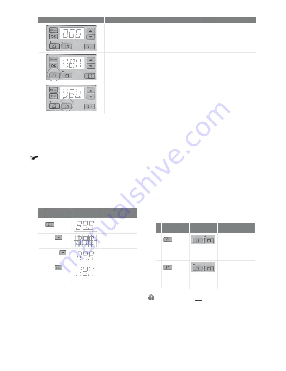
 The displayed settings are the standard setting of the unit. This may differ from the actual setting of the unit.

Appearance

Description

What to do

Three numbers with a point after the second number are 
displayed in the display. 
The current setting of the comfort temperature is displayed.

No action required.

The light above the icon with one arrow is lit.
The supply fan is turned off.
There is no supply of fresh air.

Do not forget to turn on the 
supply fan again when the supply 
fan has been turned off manually. 

The light above the icon with two arrows is lit.
The supply fan is turned on.
There is balanced ventilation.

No action required.

Содержание ComfoAir 200

Страница 1: ...Ventilation system ComfoAir Standard Manual for the user Cooling Fresh Air Clean Air Heating ComfoAir 200 ComfoAir 180 ComfoAir 550 ComfoAir 350 ComfoAir 180...

Страница 2: ...properly installed according to the instructions and guidelines in the installer manual of the unit The unit can be used by Q children aged from 8 years and above Q persons with reduced physical capab...

Страница 3: ...ng an overrun timer for the bathroom switch 9 2 7 Setting a delay timer for the bathroom switch 10 2 8 Setting the delay timer for the filter alert 10 2 9 P menus for the user 11 3 CE certification an...

Страница 4: ...EN 4...

Страница 5: ...afety regulations warnings comments and instructions given in this document Personal injury or damage to the unit can arise from non compliance with the safety regulations warnings comments and instru...

Страница 6: ...icating the set ventilation level Indicating a malfunction or filter alert Indicating if the bypass is open Turning the supply fan on and off Indicating and setting the comfort temperature Setting the...

Страница 7: ...ed Clean or replace the filters as mentioned in the Maintenance chapter The letter A is flashing at the left of the display with one or two numbers on the right of the display The current malfunction...

Страница 8: ...fireplace the unit is fitted with an open fire programme When needed the installer or service engineer can turn this programme on If the open fire programme is turned on the supply fan cannot be turne...

Страница 9: ...ed to the default screen 2 6 Setting an overrun timer for the bathroom switch The ventilation setting can be increased for a set time This can be useful when additional ventilation is needed for a sho...

Страница 10: ...alert How fast the filters of the unit need cleaning or replacing depends on the air quality of the environment In the countryside the filters may not pollute as fast as in urban places Therefore the...

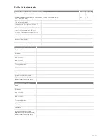
Страница 11: ...Time delay values Submenu Description Minimum Maximum General reset P21 Only applies to systems fitted with a bathroom switch Delay timer for the bathroom switch to switch to high position Q x minute...

Страница 12: ...o alter previously delivered products Liability The unit has been designed and manufactured for use in balanced ventilation systems incorporating Zehnder heat recovery systems Any other application is...

Страница 13: ...ement or any other compelling reasons If the power to the unit is disconnected mechanical ventilation of the dwelling will cease This can lead to a build up of moisture and result in problems with mou...

Страница 14: ...seconds until the filter warning disappears 2 Disconnect the power from the unit 3 A ComfoAir180 A ComfoAir 200 Remove the handles A from the unit A A ComfoAir 350 A A ComfoAir 550 4 B ComfoAir 200 B...

Страница 15: ...f the valves 4 3 Condensation drain Ensure that the water seal u bend connected to the domestic waste water system is always full of water 4 4 Maintenance by the installer or service engineer Not all...

Страница 16: ...t 2b Inspection of installation Part 3 Airflow measurement test and commissioning details Part 1 System details and declarations 1 1 Installation Address Details Dwelling name number Street Locality T...

Страница 17: ...iled here Description of installed controls e g timer central control humidistat PIR etc Location of document override controls Signature Number if applicable Date of Installation completion 2 2 Insta...

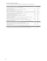
Страница 18: ...protection packaging been removed including background ventilators such that system is fully functional Yes No For ducted systems has the ductwork installation been installed in such manner that air r...

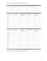
Страница 19: ...5 1b in ADF Kitchen Bathroom En Suite Utility Other Other Other 3 4 Air Flow Measurements supply system 4 only Room reference location of terminals Measured Air Flow High Rate l s Design Air Flow Hig...

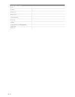
Страница 20: ...EN 20 3 6 Test Engineer s Details Name Company Address Line 1 Address Line 2 Telephone Number Post Code Signature Competent Person Scheme Registration if applicable Date of test...

Страница 21: ...hs after installation Activity Y1 Y2 Y3 Y4 Y5 Y6 Y7 Clean the filters 12 months after installation Activity Y1 Y2 Y3 Y4 Y5 Y6 Y7 Replace the filters Clean the valves Inspect and clean the condensation...

Страница 22: ...installation Activity Y8 Y9 Y10 Y11 Y12 Y13 Y14 Clean the filters 12 months after installation Activity Y8 Y9 Y10 Y11 Y12 Y13 Y14 Replace the filters Clean the valves Inspect and clean the condensatio...

Страница 23: ...23 EN...

Страница 24: ...HKQGHU RPIRV VWHPV GLYLVLRQ RI HKQGHU URXS 8 WG 8QLW URRNVLGH YHQXH 5XVWLQJWRQ HVW 6XVVH 1 7 FRPIRV VWHPV HKQGHU FR XN ZZZ HKQGHU FR XN ZGNL Manual_849050685 V0614 EN Subject to change...

Отзывы: