background image


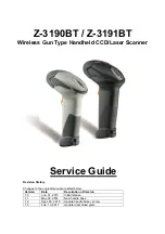
 Z-3190BT/Z-3191BT Service Guide  

7 / 11

S

ERVICE  

G

UIDE


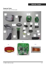
NO. P/N 

Name 

Quantity 

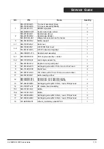
863-319000-205 

863-319000-206  

Top cover assembly (Grey) 

Top cover assembly (Black) 

510-331901-751 

ZEBEX logo plate 

602-2SSHC0-681 

Center mirror base rubber 

560-431900-001 

560-431900-002  

Handle base (Grey) 

Handle base (Black) 

540-D319X0-261 Waterproof 

protective net for buzzer 

3 564-031900-362 Button 

support 

4-1 684-100000-542  Dust 

cover 

684-100000-541 

Z-3191HS Dust cover 

4-2 

514-831910-003 

Z-3191 Laser warning label 

863-19XBT0-715 

Handle board assembly 

6-1 

863-190BT2-516 

CCD engine as rubber 

6-2 

863-191BT0-501 

Laser engine assembly 

564-031900-412 

Buyzzer sound guide panel 

521-614000-015 

Self tapping screw M3-15.0mm,round,Torx head 

9 644-7319X0-000 Mylar 

Tape 

10 

031-007016-000 

16P,0.5mm pitch FFC,L=70mm,one side contact 

11 

603-031900-581 

Button sealing rubber 

12 

863-19XBT0-817  

863-19XBT0-818 

Handle base cover assembly (Grey) 

Handle base cover assembly (Black) 

13 

521-004000-8R0 

Self tapping screw,M3-8.0mm, round, Philips head 

14 

613-190BT1-201 

BT module board assembly 

15-1 560-131901-524  Button 

15-2 560-131901-523  Button 

16 

521-003000-6R0 

Self tapping screw,M2-6.0mm, round, Philips head 

17 

521-003000-8R0 

Self tapping screw,M2-8.0mm, round, Philips head 

18 

191-B25004-201 

Lithium_ion Battery pack-NP100 


Содержание z3190BT

Страница 1: ...r Service Guide Revision History Changes to the original manual are listed below Version Date Description of Version 1 0 Jan 31 2013 Initial release 1 1 May 22 2014 New handle base 1 2 Sept 20 2015 Up...

Страница 2: ...e when operated in a commercial environment Radio and Television Interference Operation of this equipment in a residential area can cause interference to radio or television reception This can be dete...

Страница 3: ...e of procedures other than those specified herein may result in hazardous radiation exposure For CE Countries This scanner is in conformity with CE standards Please note that an approved CE marked pow...

Страница 4: ...s Preface 2 Important Notice 2 Radio Notice 2 Radio and Television Interference 2 Laser Safety 2 For CE Countries 3 Power Supply 3 WARNING 3 Introduction 5 Product Overview 5 Scanner Parts 6 Take Apar...

Страница 5: ...with a state of the art scan engine Featuring a superb scanning speed and able to withstand 1 5 meter drop it is ideal for manufacturing and logistic sectors Superb scanning ability Proprietary hardwa...

Страница 6: ...Z 3190BT Z 3191BT Service Guide 6 11 SERVICE GUIDE Scanner Parts The scanner includes the following parts 1 2 3 4 1 5 6 1 7 8 9 10 11 12 13 14 15 1 16 17 18 6 2 15 2 4 2...

Страница 7: ...engine assenbly rubber 1 6 2 863 191BT0 501 Laser engine assembly 1 7 564 031900 412 Buyzzer sound guide panel 1 8 521 614000 015 Self tapping screw M3 15 0mm round Torx head 2 9 644 7319X0 000 Mylar...

Страница 8: ...Instructions Read these instructions completely before you begin Follow all instructions Heed all warnings Tools to Prepare Philips screwdriver Please follow these steps to take apart the scanner 1 R...

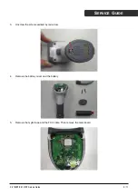
Страница 9: ...3190BT Z 3191BT Service Guide 9 11 SERVICE GUIDE 3 Unscrew the screws pointed by red arrow 4 Remove the battery cover and the battery 5 Remove the mylar tape and the FCC cable Then remove the main boa...

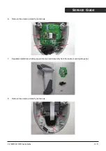
Страница 10: ...1BT Service Guide 10 11 SERVICE GUIDE 6 Remove the screws pointed by red arrows 7 Separate handle base battery power charge board assembly from the buzzer sound guide panel 8 Remove the screws pointed...

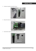
Страница 11: ...Z 3191BT Service Guide 11 11 SERVICE GUIDE 9 Separate the baseplate assembly and the button 10 Remove the screws pointed by red arrows 11 Sparate button sealing rubber base plate button support and F...

Отзывы: