ZBA ZZB88-441S Скачать руководство пользователя страница 21


ZBA Inc

.


ZBA, Inc. 

94 Old Camplain Road    Hillsborough, NJ 08844 

Ph: 908-359-2070   Fax: 908-595-0909 

Web: http://www.zbausa.com/ 


10 

Point-to-point mode Data specification  

When the module is operating in point-to-point mode the data format is based on following format. If the 
module are not configured to receive the serial data in to following format then data will be considered 
invalid. The AT+_SENDTYPE =2 is the appropriate command.  

10.1


Overview of the data packet format (point -to-point)   

Packet format is defined as the 

5

 byte header plus valid data, as follows:


Sync


Package Type


Sequence Number


Data length


Valid data


0x55


0xAA


1 Byte


1 Byte

1 Byte


(0

 - 

80)

 Bytes


1)


Sync:

 each packet by


0x55, 0xAA


start a data packet used to synchronize


2)


Package Type:

 1 byte length type field, used to indicate the type of the current packet, the case of


AT


commands or other types of packets.


Specific packet types are as follows:


Package Type


Help


Data transmission direction


0x 00


Additional


AT


Command Request


External


MCU 

Æ

 Zigbee


Module


0x01


Additional


AT


Command 

Response


Zigbee


Module


Æ


External


MCU


0x10


Packet


Two-way


0x20


Package receiving response


Zigbee


Module

Æ


External


MCU


3)


Sequence Number

: This parameter is one byte in length and it represents the sequence of commands 

form a particular module. The Serial number sequence is first set by the Zigbee module during the 
0x20 package receiving response. Each subsequent  communication the serial number will be 
incremented by one (1)    


4) 

Data length

: 1 byte of data length field, which contains the number of bytes of data.


Maximum data 

length is


80


bytes.


5) Valid data

: This field is data, and the length of the data is indicated by the previous byte. .
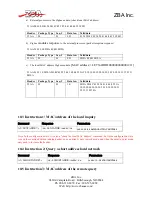
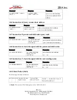
  

10.2


 Additional AT command request (0x00) & Response (0x01) Packet  


In point to point mode, the following example is used to show how to inquire the local MAC address.  This 

method can also be used to, a) 


MAC


address lookup of remote devices through a short address queries 

through the network Remote


MAC


address,  b) short address by the network of parent-child query node,  c)  

query the local node and the neighbor node signals, etc..


The following is an example of the format of the data (hex) flow between the  

Содержание ZZB88-441S

Страница 1: ...ZBA Inc 94 Old Camplain Road Hillsborough NJ 08844 Ph 908 359 2070 Fax 908 595 0909 Web http www zbausa com ZIGBEE Module with on board antenna PN ZZB88 441S User Manual Version 1 0_20090622 PCB JO 0...

Страница 2: ...ctional Interface Specification 14 7 1 Mode switch port 14 7 2 Indicator 14 7 3 Data Interface 15 7 4 Configuration Interface 16 8 The UART 17 9 Module Configuration Commands 18 9 1 Instruction 1 Test...

Страница 3: ...ZBA assumes no responsibility for any errors or omissions that may appear in this document and disclaims responsibility for any consequences resulting from the use of the information set forth herein...

Страница 4: ...multiple network topologies including self healing features point to point or point to multipoint configuration which can be composed as star tree mesh tree network structure and of course low power...

Страница 5: ...C 4 Product performance 4 1 1 Low power consumption This module can be configured in a variety of energy saving modes in which it is possible to have a fully operational system run for more than 6 mo...

Страница 6: ...ttp www zbausa com data RS232 data via the UART interface and the firmware will allow you to transmit broadcast messages to the other devices in the network Any module in the network can be queried fr...

Страница 7: ...pads according to Human Body Model JEDEC STD 22 method A114 200 V V According to Charged Device Model JEDEC STD 22 method C101 5 2 Electrical Description 5 2 1 Recommended operating voltage Name Min T...

Страница 8: ...0 5 0 A Digital regulator off High frequency RCOSC and crystal oscillator off 32 768 kHz XOSC POR and ST active RAM retention Power mode 3 0 3 A No clocks RAM retention POR active 5 4 General Charact...

Страница 9: ...quires 0 dB Alternate channel rejection 10 MHz channel spacing 55 dB Wanted signal 88dBm adjacent modulated channel at 10 MHz PER 1 as specified by 1 1 requires 30 dB Alternate channel rejection 10 MH...

Страница 10: ...0 dBm Delivered to a single ended 50 load through a balun and output power control set to 0x5F TXCTRLL 1 requires minimum 3 dBm Programmable output power range 25 8 dB The output power is programmabl...

Страница 11: ...bits ENOB 2 5 5 7 3 9 0 10 5 Bits 8 bits setting 10 bits setting 12 bits setting 14 bits setting Effective number of bits ENOB Differential input1 E TBD Offset1 TBD LSB Conversion time 20 36 68 132 S...

Страница 12: ...ZBA Inc ZBA Inc 94 Old Camplain Road Hillsborough NJ 08844 Ph 908 359 2070 Fax 908 595 0909 Web http www zbausa com 6 1 Module Pin out Figure 6 1 Pin out of the module...

Страница 13: ...List Pin No Function Type Description 1 P22 Digital I O 2 P21 Digital I O 3 GND Ground System ground 4 Vcc In Power Input 2 0V 3 6V digital power supply for digital I O 5 P20 Digital I O 6 P17 Digita...

Страница 14: ...t PIO_01 is configured as a mode switching port When the module is controlled by an external microprocessor switching this pin will allow the user to switch between the normal operation running mode a...

Страница 15: ...t P11 LED indicator is Off Central node coordinator A successful network has been created Routing node The node has Join the network Terminal node The node has Join the network Always Not connected to...

Страница 16: ...pin PIO_01 pin is connected high the system enters the command mode low on this pin will shift the module s operating mode to the operational mode The command mode will only accept command at a fixed...

Страница 17: ...serial asynchronous communication interface The following diagram shows the TXD RXD CTS RTS signals for the UART and the direction of the data flow The voltage levels of the UART are low 0 Volts and...

Страница 18: ...Para1 baud rate 1200 2400 4800 9600 19200 38400 57600 115200 230400 Default 9600 AT BAUD r n OK r n BAUD Para1 r n Note The communication parameters used during the communication mode is fixed at 9600...

Страница 19: ...truction 8 Set Query the device type Command Response Parameters AT ROLE Para1 r n OK Para1 0 The central node 1 The routing node 2 The terminal node Default 1 AT ROLE r n OK r n ROLE Para1 r n 9 9 In...

Страница 20: ...k will be able to receive the broadcast message 1 Master slave mode When operating in the Master Slave mode the serial data is sent to the central coordinator The other nodes in the network simply act...

Страница 21: ...t External MCU Zigbee Module 0x01 Additional AT Command Response Zigbee Module External MCU 0x10 Packet Two way 0x20 Package receiving response Zigbee Module External MCU 3 Sequence Number This parame...

Страница 22: ...54 41 44 44 52 3A 30 30 30 30 30 30 30 30 30 30 30 30 31 32 31 31 0D 0A Header Package Type Seq Data len Valid data 55 AA 01 01 1E 0D 0A 2B 4C 45 58 54 41 44 44 52 3A 30 30 30 30 30 30 30 30 30 30 30...

Страница 23: ...r n ASSOCDEVLIST paddr caddr r n r nOVER r n paddr parent node short address caddr child node short address 10 8 Instruction 6 check the signal with the parent and child nodes Command Response Parame...

Страница 24: ...a 55 AA 10 0C 00 01 48 65 6C 6C 6F 57 6F 72 6C 64 Special Note When the transmission of data starts the load flow of data packets can be very large it is recommended to enable the module s flow contro...

Страница 25: ...er the area where the antenna is located A ground plane directly underneath the antenna region will drastically reduce the range of the module The absolute minimum nearest ground plane should be 3mm a...

Страница 26: ...four zones 1 Preheat Zone This zone raises the temperature at a controlled rate typically 1 2 5 C s 2 Equilibrium Zone This zone brings the board to a uniform temperature and also activates the flux 3...

Страница 27: ...her profiles that you may require 13 Operational Notes 1 This product is not waterproof do not install the product directly to outdoor and damp places 2 This product is a wireless electronic products...

Отзывы: