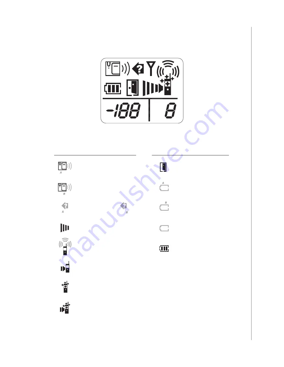
Zartek ZA-601 Скачать руководство пользователя страница 5

4

LCD Icons

• Light up continuously

Flashing

Icon

I

Door lock opened

J

ontgate battery low

K

Backgate battery low

L

Self battery low

M

Battery level

Volume/door chime loudness

Status

Icon

Status

A

Frontgate doorbell ringing

B

Backgate doorbell ringing

C

Missed call (Frontgate)        •

(Backgate)

D

Conversation mode

F

Door chime alert selected

G

Flashing light alert selected

H

Door chime and flashing light alert selected

Outdoor

A B

E

CH

˚C

˚F

Содержание ZA-601

Страница 1: ......

Страница 2: ......

Страница 3: ...by yourself Please read this manual carefully to obtain optimum performance and extended service life from the system For any queries please contact Zartek via email info zartek co za Features Digital...

Страница 4: ...button 13 Volume down button 14 Door chime melody select button 22 Battery contact spring 23 Battery cover lock button 24 Charger contact plates 25 Charging indicator 26 Full charge indicator 27 Charg...

Страница 5: ...elf battery low M Battery level Volume door chime loudness Status Icon Status A Frontgate doorbell ringing B Backgate doorbell ringing C Missed call Frontgate Backgate D Conversation mode F Door chime...

Страница 6: ...er Unit e Rechargeable Ni MH battery pack h Screws and rivets c Charger stand f Mounting bracket i Instruction manual a b d c e f g h i Setting the operating channel Outdoor Caller Unit CALL CH C Outd...

Страница 7: ...With the help of a pointed object set the position of the white colour dip switches 6 to one of the following 1 and 2 ON for CH 1 1 OFF and 2 ON for CH 2 1 ON and 2 OFF for CH 3 1 and 2 OFF for CH 4...

Страница 8: ...rm channel selection Selected handset channel must correspond to operating channel on the gate station Handset 1 Remove the battery cover by pressing down the lock button 23 2 With the help of a point...

Страница 9: ...gets dark the name plate will be automatically illuminated if a AC DC supply is connected although not with a battery supply only Battery supply Insert four AA alkaline cells into battery compartment...

Страница 10: ...rger stand will cause no damage to the battery In the latter case when the battery is being consumed and voltage falls to a certain level the charger stand will automatically charge up the battery The...

Страница 11: ...n Pairing the Handset and Caller unit Handset Caller unit 9 8 7 CALL OFF ON CHANNEL NORMAL PAIRING 1 2 3 Step 2 Step 3 CALL CALL 2 2 1 Insert four UM 3 alkaline cells into battery compartment Observe...

Страница 12: ...e above If programming a four button caller unit be sure to press the appropriate button see above that corresponds to the channel on the handset as all channels are already allocated to buttons Set d...

Страница 13: ...handset or caller unit for backgate use it is necessary to perform the cloning process or otherwise the new units will not work with your original system Handset Cloning procedures Ensure that the ha...

Страница 14: ...te with the original channel the handset s channel will need to be changed Programming the Back Gate By default all caller units are front gate caller units station A An internal modification is neede...

Страница 15: ...LL button 10 icon E appears in LCD The stored ID code will be transmitted and two di sound will be heard periodically CALL 10 Di Di CH C Outdoor CALL 8 CH C Outdoor 7 OFF ON CHANNEL NORMAL PAIRING 1 2...

Страница 16: ...ber to set the yellow dip switch 7 back to NORMAL position after pairing or cloning procedures otherwise the caller unit will not operate properly Gate opening AC or DC voltage of 8 12V is needed in o...

Страница 17: ...ds to the power slots at the back of the caller unit There is no required polarity for the AC connections Procedure 1 Insert 4 AA batteries not included into the battery slots The LED indicator 2 shou...

Страница 18: ...is also needed a relay board GE 247 which does have a specific DC polarity requirement will interface to the gate controller Please see the diagrams below for the 2 options to connect using DC power...

Страница 19: ...e unlock round button 11 on the handset once the channel is open The LED light on the relay board will light up when the gate motor is triggered Option B Procedure 1 Connect pin 1 on caller unit to 12...

Страница 20: ...gate purchased optionally caller units are installed Wrong setting may lead to false alarm of out of range alert Making receiving calls Make sure there is power supply to the caller unit either by 8 1...

Страница 21: ...units will ring and can answer to the call However only the unit who first press the button 9 can reply to the call all others will be excluded from the intercom Handsets under intercom may not be ab...

Страница 22: ...an stop the alarm but the icon J or icon K still remains until new batteries are installed The outdoor temperature indication provides you with an idea about the weather which is useful if you plan to...

Страница 23: ...y is available c Make proper connection Cannot perform intercom between Handsets a The ID code is not properly cloned to the slave units b Battery has run down c Operate on different channel a Perform...

Страница 24: ...his manual can be helpful in drilling the correct position of holes 6 Align the two rivets on the mounting bracket with the holes of the metal hangers on the back of the caller unit make contact and s...

Отзывы: