4.3 Special notes
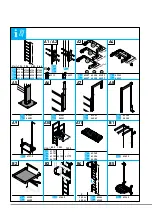
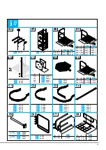
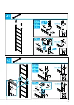
The installation instructions are presented in the form of diagrams.
For installation instructions,
see the illustrations section,
A1
to
C9
The following must also be observed:
– Safety instructions in the section "Safety instructions" (p. 38).
– The notes below on the individual installation steps.
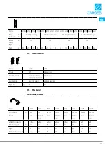
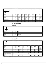
Double-sided wall brackets (U-shaped bar that fixes both sides of the ladder), single-sided wall brackets
– Check that the surface of the substructure is flat and perpendicular; use adjustable
wall brackets if necessary.
– Mount each ladder segment with at least two double-sided U-shaped bars or four
single-sided wall brackets.
• If you intend to install the wall brackets using a screw anchor system, only use ones
that have been approved by the building control authority. The company carrying out
installation is responsible for the work and must examine the masonry thoroughly.
If you are unsure of anything, contact an expert in structural engineering or a technical
consultant from the manufacturer of the screw anchors (mandatory in accordance
with DIN 14094-1). The attachment hardware of each wall bracket must be able to
withstand a total pull-out force of ≥3 kN and, when used in combination with a fall
arrester system (e.g. the ZARGES ZAST fall arrester system), an impact force of ≥6 kN.
Screw anchors are not included in the scope of delivery.
• Standard static calculations are available for wall brackets ..257, ..258, ..259, ..260.
For wall brackets ..261, ..262, static calculations must be requested individually
for each construction project.
• For version with security door:
– Do not attach wall brackets in the area of the hinge attachments.
• For version with emergency exit ladder:
– Countersink drilled hole for attachment of the fixed ladder.
– Use countersunk head screws.
– Restore anti-corrosion protection in the area of the countersink.
Ground plate
Two ground plates can be used instead of the bottom wall bracket.
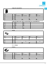
Landing rail (with floor bracket)
• Use only in combination with stile extension (43243/44243).
Landing rail, angled
• Mandatory within the area of application of DIN 14094-1.
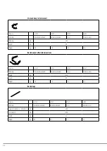
Landing with crossover
The crossovers are designed for a maximum moving working load of 150 kg. They are not
designed as collection or storage points for increased working loads or stationary loads.
The exit ladder must be attached to the building using wall brackets or ground plates.
Installation with ground plates is described in the illustrations section.
If fall protection (guardrails) is required at the sides (e.g. to comply with DIN 18799-3),
it must be provided by the operator.
A3-A4
A5
A8
A10
40
Содержание 41286
Страница 56: ...4 3 A3 13 332 mm 1 2 3 3 M8 M8x24 3 kN 3 kN 2 m 4 3 A4 13 332 mm 334 mm 577 mm 1 2 3 3 M8 M8x24 2 m 3 kN 3 kN...
Страница 61: ...4 3 B2 1 2 13 17 5 Nm 2 2 1 M8 M8 M8x65 2 1 3 17 5 Nm 4 3 B3 1 2 1 3 61...
Страница 63: ...4 3 B5 1 2 M8 M8 17 5 Nm M8 M8 13 2x 17 5 Nm 1 1 2 2 4 3 B6 1 2 M8 M8 17 5 Nm 1 2 13 2x A19 63...
Страница 64: ...4 3 B7 1 M8 M8 17 5 Nm 2 13 2x...
Страница 67: ...4 3 B10 1 3 2 17 2x M10 M10x80 M10 M10x160 R16x2x40 35 Nm 35 Nm 4 3 B11 1 2 B8 B9 B13 B8 B9 B13 1 2 17 67...
Страница 68: ...4 3 B12 1 2 3 1 2 13 17 5 Nm 0...
Страница 70: ...4 3 C1 C2 C4 1 2 17 13 2x 1 2 3 35 Nm 2 1 3 17 5 Nm M8x20 M8 M8 M8x20 1 0 m 2 2 3 0 m C2 120 mm C1 C2 C4 13...
Страница 71: ...4 3 C6 1 2 17 5 Nm 2 1 13 2x 2 3 M8 1 1 m 1 C3 17 M10 M10x25 1 2 3 35 Nm 520 620 29 1340 520 100 1 6 m 0 71...
Страница 72: ...4 3 C8 13 2x 1 2 10x 1 2 3 4 4 3 C7 13 2x 1 2 1 1 2 4 3 17 5 Nm 5 5 6 17 5 Nm...
Страница 73: ...4 3 C9 10 73...

