Page 9
2.6 SEM2 CHOPPER DIAGNOSIS
The microprocessor continually monitors the chopper and carries out diagnostic proce-
dures on the main functions.
The diagnosis is made in 4 points:
1) Diagnosis on key Switch closing that checks: the Watch Dog Circuits, the current
sensor, VMN point, Contactor Drivers, the switch sequence for operation is correct,
and the output of the accelerator or tiller is correct.
2) Standby Diagnosis at rest that checks: VMN Point, Contactor Drivers, and Current
Sensor.
3) Diagnosis during operation that checks: Watchdog, VMN Point, Current,
Contactor(s), and VMN when in full conduction.
4) Continuos Diagnosis that checks: Chopper temperature, Battery Voltage.
Diagnosis is provided in 2 ways. The Red Led connected to Connector A will flash a
certain number of times for a given Alarm (See Listings), or the Digital Console may be
used. A permanent Alarm will be displayed on the Console immediately and the RED
LED will flash. An intermittent Alarm will be recorded in the Alarm library, but the RED
LED will only flash at the time of the Alarm.
2.7 THERMAL CONSIDERATIONS.
- The heat generated by the power block must be dissipated. For this to be possible,
the compartment must be ventilated and the heat sink materials ample.
- The heat sink material and system should be sized on the performance requirement
of the machine. Abnormal ambient air temperatures should be considered. In situa-
tions where either ventilation is poor, or heat exchange is difficult, forced air ventila-
tion should be used.
- The thermal energy dissipated by the power block module varies and is dependent
on the current drawn and the duty cycle.
Содержание SEM2
Страница 15: ...Page 15 3 6 MECHANICAL DRAWING DIMENSIONS...
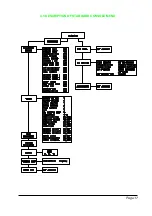
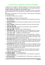
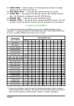
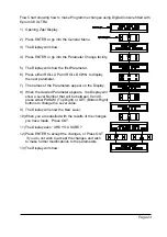
Страница 17: ...Page 17 4 3 DESCRIPTION OF STANDARD CONSOLE MENU...
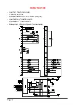
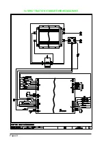
Страница 24: ...Page 24 5 4 SEM 2 TRACTION STANDARD WIRING DIAGRAMS...
Страница 38: ...INSTALLATION AND USER MANUAL CHOPPER SEM2...


