Zapi SEM-Zero Скачать руководство пользователя страница 34

Page 34

6.4 DESCRIPTION OF CONSOLE RESTORE FUNCTION.

The RESTORE PARAM function allows transfer of the Console’s stored data into the
memory of the chopper.  This is achieved in a fast and easy way using the method
previously used with the SAVE PARAM. function.
The data that are available via the RESTORE PARAM. function are as follows :
- All Parameter Values (PARAMETER CHANGE).

- Options (SET OPTIONS)

- The level of the Battery (ADJUST BATTERY)

ATTENTION: When the RESTORE operation is made, all data in the chopper memory
will be writtten over and replace with data being restored.
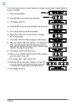
Flow Chart showing how to use the RESTORE function of the Digital Console.

1) Opening Zapi Display.

2) Press ENTER to go into the General menu.

3) The Display will show :

4) Press either ROLL UP or ROLL DOWN

button until

RESTORE PARAM. appears on the display.

5) The Display will show :

6) Press ENTER to go into the RESTORE PARAM. function.

7) The Display shows the type of Model stored,

with a Code Number.

8) Keep pressing either ROLL UP and ROLL DOWN buttons

until the desired model appears on the Display.

9) The model is shown

10) Press ENTER to commence the Restore operation.

11) The Display will ask “ARE YOU SURE”.

Press  ENTER for YES, or  OUT for No.

12) Press ENTER to confirm (OUT to not confirm)

13) You can see the items that are being stored in

the chopper memory whilst the RESTORE
routine is happening.

14) When finished the Console displays :

15) Press OUT to return to the Opening Zapi Display .

MENU

Содержание SEM-Zero

Страница 1: ...onsole 15 4 1 Adjustments via Console 15 4 2 Description of Console Connection 15 4 3 Description of Standard Console Menu 16 5 SEM Zero cabling and configuration 17 5 1 Power diagram 17 5 2 Connectio...

Страница 2: ...Page 2 SIGNED IN APPROVAL COMPANY DEPT SERVICES MANAGEMENT EXECUTIVE ENGINEERING SECTION EXECUTIVE EXPORT MANAGER Pubblicazione n ACLZP0CA Edizione Aprile 1998 MENU...

Страница 3: ...tor NPC Negative Pump Contactor NPOT Negative Potentiometer PC Pump Contactor PEMB Positive Electromechanical Brake PEV Positive Lowering Valve PHORN Positive Horn PMC Positive Main Contactor PPC Posi...

Страница 4: ...ious chopper configurations can be selected by the user without the need for hardware modifications Future technological updates are made easy for the user The communication protocol will continue to...

Страница 5: ...ENT BOOSTER CURRENT VOLTAGE DROP IN FULL CONDUCTION 24 36V 150A 3 180A 10 0 23V at 50A 25 C 24 36V 200A 2 230A 10 0 23V at 50A 25 C 2 2 CONTROL UNITS 2 2 a Microswitches Microswitches should have a co...

Страница 6: ...n in either direction This function is unique when it is necessary to compensate for asymmetry with the machanical elements associated with the potentiometer especially relating to the minimum level T...

Страница 7: ...nce if these operations are not carried out correctly Requests for drive must be made after closing the key Switch Protection against uncontrolled movements The Line Contactor will not close if The Po...

Страница 8: ...witch is closed if the motor is rotat ing the chopper controls the speed and automatically brakes and keeps the motor at a very low speed during descent on a gradient This is a very useful safety feat...

Страница 9: ...Led connected to Connector A will flash a certain number of times for a given Alarm See Listings or the Digital Console may be used A permanent Alarm will be displayed on the Console immediately and...

Страница 10: ...by a traction battery Do not use the outputs of converters or power supplies For special applications please contact the nearest Zapi service centre Start the machine the first time with the drive wh...

Страница 11: ...onnections to the motor armature and battery use cable of 16mm section For the Field connections use cable of 4mm section For the optimum chopper performance the cables to the battery should be run si...

Страница 12: ...W HORN LIFT LOW microswitches A8 H S Hard Soft function input It should be connected to A7 through the H S switch Active high VB B1 CPOT Accelerator s potentiometer wiper or output of inductive device...

Страница 13: ...C Positive pump contactor it should be connected to A7 by lifting micro switch LIFT which provides the positive supply to the pump contactor s coil D5 NPC NEV Negative supply for pump contactor D6 PEV...

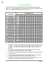
Страница 14: ...Page 14 3 6 MECHANICAL DRAWING DIMENSIONS MENU...

Страница 15: ...ing the Digital Console The Console is connected to the E connector of the SEM Zero Chopper Pay attention to the polarity of the Console Connector when connecting to the chopper The bevel on the conne...

Страница 16: ...Page 16 4 3 DESCRIPTION OF STANDARD CONSOLE MENU MENU...

Страница 17: ...Page 17 5 SEM ZERO CABLING AND CONFIGURATION 5 1 POWER DIAGRAM MENU...

Страница 18: ...Page 18 5 2 CONNECTIONS MENU...

Страница 19: ...hourmeter If the pump contactor is connected D4 hourmeter output A1 is activated during lifting as well 2 QUICK INVERSION BELLY Quick inversion is activated while the Belly Button is pressed TIMED Qui...

Страница 20: ...the menu appears on the Display 8 Press either ROLL UP or ROLL DOWN to bring up the next the Option 9 A new Option appears on the Display 10 When the desired Option is displayed press PARAM Top Right...

Страница 21: ...e 6 SOFT ACCEL Determines how much the acceleration ramps are reduced when the H S function is active 7 CUTBACK SPEED 1 First speed reduction 8 CUTBACK SPEED 2 Second speed reduction 9 H S CUTBACK Spe...

Страница 22: ...8 FIELD NOM CURR Nominal Field Current This parameter fixes the minimum Field Current when the potentiometer is between 0 and 60 without total conduc tion of the Armature Adjustment should be made wit...

Страница 23: ...0 1 2 3 4 5 6 7 8 9 COMPENSATION IA 0 5 10 16 22 27 33 38 44 78 MAXIMUM CURRENT IMax 82 84 86 88 90 92 94 96 98 100 ARMA CUR NOM ACN IMax 45 47 50 52 54 56 58 61 63 65 WEAK DROP OUT ACN 40 44 48 52 5...

Страница 24: ...e names of the Parameters appear on the Display 8 When the desired Parameter appears the Display will show a Level Number that will be between 0 and 9 press either PARAM Top Right or SET Bottom Right...

Страница 25: ...Page 25 5 4 SEM ZERO TRACTION STANDARD WIRING DIAGRAMS MENU...

Страница 26: ...t the CREEP level starting from level 0 The machine should just move when the accelerator microswitch is closed Increase the Level accordingly 8 Set the Speed Reductions as required Make adjustments t...

Страница 27: ...K Problem with Chopper 3 VFIELD NOT OK Problem with Field Voltage 4 VACC NOT OK Potentiometer Wiper 4 PEDAL WIRE KO Pedal wire not OK 5 NO FIELD CUR Field wiring not OK or field current sensor not OK...

Страница 28: ...led b Error in the starting sequence from the operator c Error in the wiring 5 FORW BACK This check is made continually The alarm is generated when forward and reverse direction are requested simultan...

Страница 29: ...or PPOT are open circuit 11 STBY I HIGH This test is made during the initial diagnosis and at standby The test verifies that the current is zero This Alarm disables the machine Possible causes a defec...

Страница 30: ...16 TH PROTECTION If the temperature of the chopper rises higher than 70 C this alarm is generated The chopper current is reduced in proportion to the increase in temperature At 80 C the chopper total...

Страница 31: ...level is shown on the Left Hand Side of the Console Display and the value in percentage is shown on the Right Hand Side 8 FORWARD SWITCH the level of the Forward direction digital entry MA pin B6 ON...

Страница 32: ...the TESTER function 7 The first variable to be tested is shown on the Display 8 Press either ROLL UP or ROLL DOWN buttons until your desired variable for measurement appears on the Display 9 Next var...

Страница 33: ...showing how to use the SAVE function of the Digital Console 1 Opening Zapi Display 2 Press ENTER to go into the General menu 3 The Display will show 4 Press either ROLL UP or ROLL DOWN button until SA...

Страница 34: ...Digital Console 1 Opening Zapi Display 2 Press ENTER to go into the General menu 3 The Display will show 4 Press either ROLL UP or ROLL DOWN button until RESTORE PARAM appears on the display 5 The Di...

Страница 35: ...ing Zapi Display 2 Press ENTER to go into the General menu 3 The Display will show 4 Press ROLL UP or ROLL DOWN button until PARAMETER CHANGE appears on the display 5 The Display will show 6 Press ENT...

Страница 36: ...until PROGRAM VACC appears on the display 5 Tthe Display will show 6 Press ENTER to go into the PROGRAM VACC routine 7 The Display will show the minimum and maximum values of potentiometer wiper outpu...

Страница 37: ...519 Protected 150A Fuse C16503 Protected 200A Fuse C16520 6 3A 5x20mm Control Circuit Fuse P99060 Red LED C12372 8 Way Molex Connector C12416 6 Way Molex Connector C12371 3 Way Molex Connector C12769...

Страница 38: ...el Check every 3 months Check the mechanical operation of the Contactor s Moving contacts should be free to move without restriction Check every 3 months Checks should be carried out by qualified pers...

Страница 39: ...INSTALLATION AND USER MANUAL CHOPPER SEM ZERO ELECTRONIC INDUSTRIAL DEVICES 42028 POVIGLIO R E Via Parma 59 ITALIA Tel 0522 960050 r a Tlx 530021 AINDRE I Fax 0522 960259 MENU...

Отзывы: