24
Electrical connection
Before plugging in, ensure that the voltage and
frequency shown on the serial number plate
correspond to your domestic power supply.
Voltage can vary by ±6% of the rated voltage.
For operation with different voltages, a suitably sized
auto-transformer must be used.
Important
The appliance must be earthed.
The power supply cable plug is provided with a
contact for this purpose.
If the domestic power supply socket is not
earthed. connect the appliance to a separate
earth in compliance with current regulations,
consulting a specialist technician.
The Manufacturer declines all responsibility if the
above safety precautions are not observed.
Attention!
It must be possible to disconnect the appliance
from the mains power supply; the plug must
therefore be easily accessible after installation.
This appliance complies with the following
E.E.C. Directives:
- 87/308 EEC of 2/6/87 relative to radio interference
suppression.
- 73/23 EEC of 19.2.73 (Low Voltage Directive) and
subsequent modifications;
- 89/336 EEC of 3.5.89 (Electromagnetic
Compatibility Directive) and subsequent
modifications.
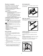
Grid preparation
Remove the grid from the appliance pulling it towards
you with hands.
Right door opening:
Remove the left side (A) of the grid cutting it from the
rear (see figure, a).
Left door opening:
Remove the right side (B) of the grid cutting it from
the rear (see figure, b).
To reposition the grid on the appliance proceed as
follows:
Apply the grid to the base of the appliance by pushing
the clasps (a) until they click.
N.B. The grid is to be assembled after having fixed
the appliance in the niche with the brackets.
S.I.002
A
B
a
b
S.I.001
a
a
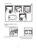
Door reversal
The appliance must be unplugged before starting
work. To reverse the opening direction of the door,
proceed as follows:
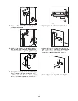
1. Remove the top hinge (1) taking care not to let the
door fall.
2. Remove the bottom door hinge (2).
3. Take out the plugs (3) from the holes (F) and
reinsert them in the holes (F
1
) on the opposite
side.
4. Refit the upper hinge (1) on the opposite side, on
the bottom (position A).
5. Refit the door on the pin of the hige (1) in position
A;
6. Insert the pin of the previously removed bottom
hinge (2) in the upper hole (G) of the door,
therefore fix the hinge on the top in position B.
S.I.003
F
F
B
A
F
3
1
2
G
1
F1
Содержание ZU 9144
Страница 14: ......


