background image

4. INSTALLATION 


CITIZEN EP70 

15 


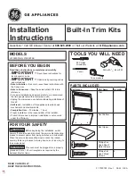
F [mm]  G [mm]  H [mm]  I [mm]  L [mm]  M [mm]  N [mm] 

CITIZEN EP70  

single-chamber 

535 

455 

350 

990 

455 

455 

693 

CITIZEN EP70  

double-chamber 

535 

455 

590 

990 

455 

455 

693 


*


N.B. When the unit is consigned without top, it is supplied with a 

vapor exhaust connector (for Ø155mm tubing)  


  Check  that  the  exhaust  system  creates  an  adequate  draft  for 

expelling vapors and cooking odors (see paragraph 4.5).


4.6 

Checks before starting up


After  completing  installation  of  the  unit  a  series  of  checks  must  be 

carried out, listed as follows: 


1. check that the various disassembled parts have been assembled: 

- vapour exhaust connection, in the case of module without top (see Fig. 

4.4 position C) 

- condensation exhaust (see Fig 4.4 position D) 
- refractory surfaces (see Fig 4.6) 

2. check the power cable 
3. check that the control panel is working 
4. If present, check that the ventilation hood is working  


N.B.  Insert  the  refractory  surfaces  with  the  corrugated  surfaces 

facing downwards. 


Fig.4.6 Positioning the slabs of refractory material

Содержание CITIZEN EP 70/4

Страница 1: ...i installazione uso e manutenzione Manual for installation use and maintenance Manual de instalaci n uso y manutenci n Notice d installation d utilisation et d entretien INSTALLATIONS BEDIENUNGS UND I...

Страница 2: ......

Страница 3: ...rom cooking appliance 13 4 6 Checks before starting up 15 5 WORKING 16 5 1 Control panel 16 5 1 1 General 16 5 1 2 Temperature control 16 5 2 Control description 16 5 2 1 Main ON OFF switch 16 5 2 2 B...

Страница 4: ...Ordinary maintenance work 22 8 1 1 Light replacement 22 8 2 Safety thermostat 23 8 3 Electrical diagram 24 8 4 Adjustment for different feed voltages 24 8 4 1 Cabling of wires to the resistor 24 8 4...

Страница 5: ...he heat The modular CITIZEN EP70 oven with single chamber and double chamber is built as a single compact unit and of modern design This design ensures a large production in a small space and at lower...

Страница 6: ...read both by the installers and by the final user and any of his staff who may use the equipment The manufacturer shall not be held liable for any damage which may occur as a result of failure to obse...

Страница 7: ...vides all the information required for the cleaning of the equipment i e all those operations which have to be carried out by the user in order to ensure that the equipment continues to function safel...

Страница 8: ...CE Regulation for Equipment intended to come into Contact with Foodstuffs 3 3 Envisaged use The electric oven mod CITIZEN EP70 has been designed to cook pizzas and delicatessen products in pans or di...

Страница 9: ...4 4 n Electrical feed three phase neutral three phase single phase neutral Frequency 50 o 60 Hz Voltage 400 3N 230 3 230 1N Vac 11 2 kW 5 6 kW Version Total electrical power 11 2 5 6 kW Current 16 2...

Страница 10: ...r sheet of nylon to protect them from shocks and humidity during transit and are delivered to the importer in the best possible condition We recommend however that the packaging is checked on arrival...

Страница 11: ...e cooling apertures Figure 4 1 The equipment must in any case be installed at least 2 cm from the walls of the room and from other equipment Finally it is necessary to ensure that the temperature and...

Страница 12: ...between the forks and the module itself Take care that children do not play with the packaging materials e g plastic sheeting and Styrofoam suffocation danger a mm b mm c mm CITIZEN EP70 single chamb...

Страница 13: ...motor while the differential device must be set to the 30 mA current see 3 The manufacturer shall not be liable for any damage which results from failure to observe the above mentioned norms See figu...

Страница 14: ...rmation plate for the module without top Fig 4 5 Point of entry for the electrical cable the vapour exhaust outlet the condensation exhaust outlet and of the information plate for the module with a to...

Страница 15: ...hecks before starting up After completing installation of the unit a series of checks must be carried out listed as follows 1 check that the various disassembled parts have been assembled vapour exhau...

Страница 16: ...side of the oven see paragraph 5 2 4 5 1 2Temperature control Oven roof temperature regulator and light Oven bedplate temperature regulator and light 5 2 Control description 5 2 1Main ON OFF switch W...

Страница 17: ...mperature regulator by probe controls the temperature of its own heating element If the temperature regulator is set on 200 C the heating element will operate until the temperature of 200 C is reach O...

Страница 18: ...o HEAT IT GRADUALLY IN ABOUT 5 6 HOURS 1 h 100 C 2 3 h 150 C 4 h 200 C 5 h 250 C 6 h 300 C The max temperature has to be reached at the end of this pre heating phase This procedure is absolutely neces...

Страница 19: ...st after loading the oven it is normal for there to be a fall in the temperature of the oven of as much as 20 30 C This should not be considered a limitation of the oven but as a useful indication tha...

Страница 20: ...e to use abrasives abrasive sponges and such like as they may in the long term diminish the shine of stainless steel parts and of glass It is better to wash the various removable parts before the food...

Страница 21: ...and damage to create a danger of electrocution and or sudden ups of the equipment 7 4 Cleaning the external surface Use a soft damp sponge to clean if necessary with a light non abrasive detergent the...

Страница 22: ...the equipment s feed cable plug is disconnected from the switchboard Put the plug in a place where the maintenance operator can easily ascertain during all of the work done with the guards removed tha...

Страница 23: ...nes when the temperature in the chamber goes above 500 C and de activates the resisters The safety thermostat has a manual reset and is sited inside the right hand panel To correct the error unplug th...

Страница 24: ...be made 1 to the cabling for the resistor wires 2 to the cabling for the feed to the control panel 3 to the application of a new label Carry out three alterations with care as otherwise the equipment...

Страница 25: ...8 MAINTENANCE CITIZEN EP70 25 Fig 8 1 Electrical diagram Citizen EP70 single chamber at 400 Vac 3 N version...

Страница 26: ...8 MAINTENANCE 26 CITIZEN EP70 Fig 8 2 Electrical diagram Citizen EP70 single chamber at 230 Vac 3 version...

Страница 27: ...8 MAINTENANCE CITIZEN EP70 27 Fig 8 3 Electrical diagram Citizen EP70 single chamber at 230 Vac 1 N version...

Страница 28: ...8 MAINTENANCE 28 CITIZEN EP70 Fig 8 4 Electrical diagram Citizen EP70 double chamber at 400 Vac 3 N version...

Страница 29: ...NANCE CITIZEN EP70 29 Fig 8 5 Electrical diagram Citizen EP70 double chamber at 230 Vac 3 version N B For double chamber ovens CITIZEN EP 70 version 230Vac 1 N see paragraph 8 3 and Electrical diagram...

Страница 30: ...DOOR FRAME PORT0513 PORT0513 4 HANDLE TUBE MANI0105 MANI0105 5 INTERNAL DOOR PORT0470 PORT0470 6 DOOR GLASS CRIS0026 CRIS0026 7 REFRACTORY SURFACE REFR0031 REFR0031 8 LEFT SIDE FIAN0573 FIAN0569 9 TOP...

Страница 31: ...8 MAINTENANCE CITIZEN EP70 31 Figure 8 7 Exploded view...

Страница 32: ...MMQ ELET0720 ELET0720 5 CLAMP LOCK ELET0036 ELET0036 6 LAMP HOLDER LAMP0021 LAMP0021 7 HALOGEN LAMP LAMP0045 LAMP0045 8 SAFETY THERMOSTAT 500 C TERM0005 TERM0005 TERM0076 TERM0076 9 CONTROL SWITCH ELE...

Страница 33: ...8 MAINTENANCE CITIZEN EP70 33 Figure 8 8 Exploded view of electrical parts...

Страница 34: ...8 MAINTENANCE 34 CITIZEN EP70 Figure 8 9 Exploded view of electrical parts...

Страница 35: ...see table 4 1 indicated in the chapter INSTALLATION 4 The machines are made up of the following materials stainless steel coated steel sheets plastic material and electrical parts For the purposes of...

Отзывы: