Getting Started
23
•
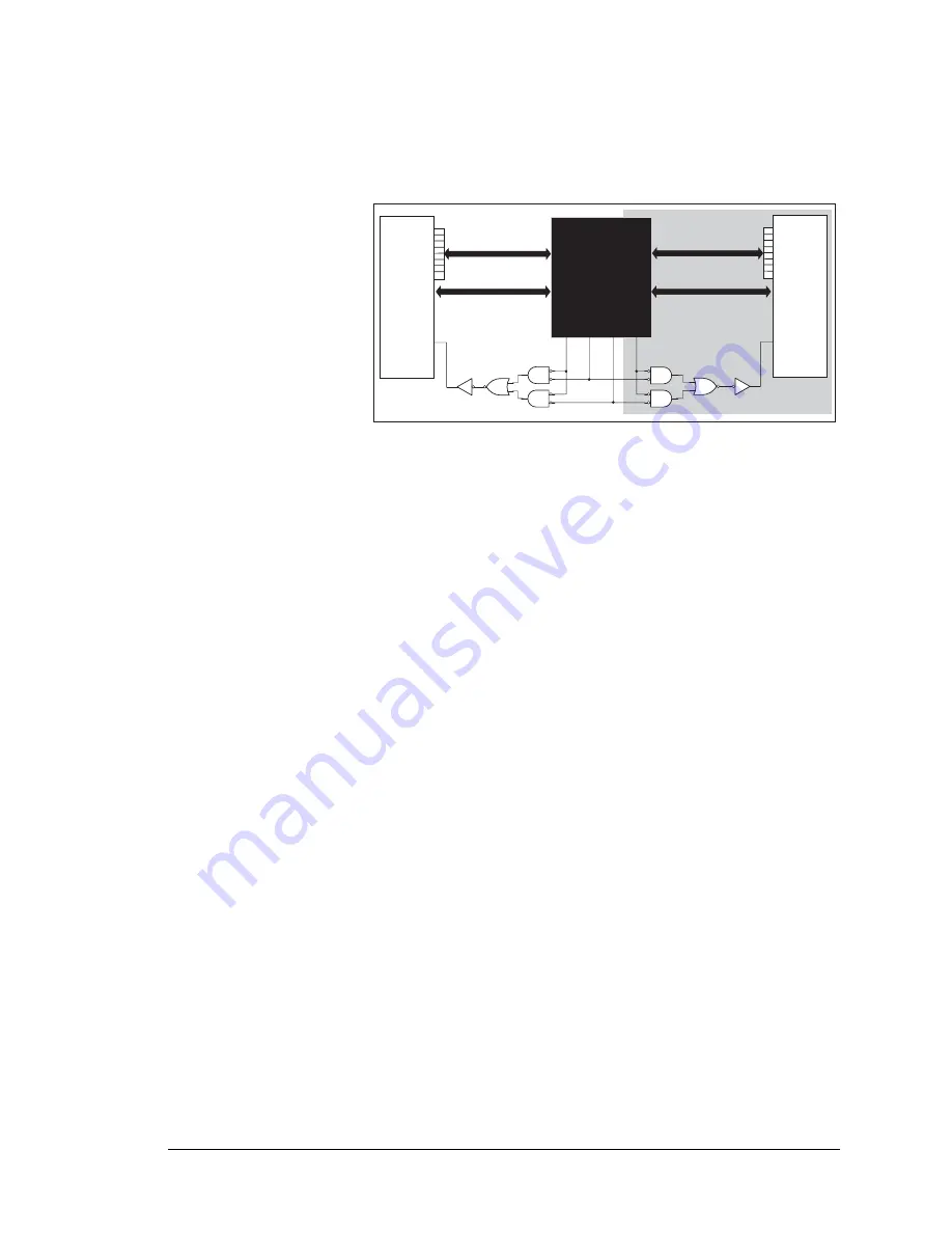
LCD_DEMO.C
—demonstrates a simple setup for an LCD that uses the HD44780 con-
troller or an equivalent.
Connect the LCD to the RCM2100 address and data lines on the Prototyping Board.
BD0—DB0
BD1—DB1
BD2—DB2
BD3—DB3
BD4—DB4
BD5—DB5
BD6—DB6
BD7—DB7
BA0—RS (Register Select: 0 = command, 1 = data)
BA1—R/W (0=write, 1=read)
*—E (normally low: latches on high-to-low transition)
•
SWTEST.C
—demonstrates the use of pushbutton switches S2 and S3 to toggle LEDs
DS2 and DS3 on the Prototyping Board on and off.
Parallel Port A bit 0 = LED DS2
Parallel Port A bit 1 = LED DS3
Parallel Port B bit 2 = switch S2
Parallel Port B bit 3 = switch S3
•
TOGGLELED.C
—demonstrates the use of costatements to detect switch presses using
the press-and-release method of debouncing. As soon as the sample program starts run-
ning, LED DS3 on the Prototyping Board (which is controlled by PA1) starts flashing
once per second. Press switch S2 on the Prototyping Board (which is connected to PB2)
to toggle LED DS2 on the Prototyping Board (which is controlled by PA0). The push-
button switch is debounced by the software.
RCM2100
Prototyping Board
2x20 LCD
E
BD0BD7
DB0DB7
25
/PE0
37
/BIOR
36
/BIOW
2x20 LCD
E
BD0BD7
DB0DB7
24
/PE1
BD7BD0 are pins 1017
on header J2
HEADER J2:
BA1BA0 are pins 2324
on header J4
BA0BA1
BA0BA1
Содержание RabbitCore RCM2100 Series
Страница 1: ...RabbitCore RCM2100 C Programmable Module with Ethernet Getting Started Manual 019 0093 050505 F ...
Страница 34: ...30 RabbitCore RCM2100 ...
Страница 52: ...48 RabbitCore RCM2100 ...
Страница 54: ...User s Manual 50 ...
Страница 56: ......


