84
Fox (LP3500)
B.2.2 Demonstration Board
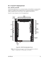
The Prototyping Board is actually both a demonstration board and a prototyping board.
As a demonstration board, it can be used to demonstrate the functionality of the LP3500
right out of the box without any modifications to either board. There are no jumpers or dip
switches to configure or misconfigure on the Prototyping Board so that the initial setup is
very straightforward.
The Prototyping Board comes with the basic components necessary to demonstrate the
operation of the LP3500. Four LEDs (DS1–DS4) are connected to PD0–PD3, and four
switches (S1–S4) are connected to PE0, PE1, PE4, and PE5 to demonstrate the interface to
the Rabbit 3000 microprocessor.
NOTE:
Before running sample programs based on the LP3500, you will have to plug in
the LP3500 to the Prototyping Board as described in Chapter 2, “Getting Started.”
B.2.3 Prototyping Area
Small to medium circuits can be prototyped using point-to-point wiring with 20 to 30 AWG
wire on the prototyping area. Raw DC input, VIN, and GND lines surround the prototyp-
ing area.
The resistor pack located next to the pushbutton switches may be removed to disconnect
the LEDs and pushbutton switches from the Prototyping Board circuits, giving your
LP3500 exclusive access to what you may develop in the prototyping area.
+K and VIN are tied together by resistor R1 located beside header J44. Cut off R1 if you
intend to supply a seK.
Содержание Fox LP3500
Страница 1: ...Fox LP3500 C Programmable Single Board Computer User s Manual 019 0111 041029 E ...
Страница 6: ...Fox LP3500 ...
Страница 14: ...8 Fox LP3500 ...
Страница 22: ...16 Fox LP3500 ...
Страница 86: ...80 Fox LP3500 ...
Страница 120: ...114 Fox LP3500 ...
Страница 130: ...124 Fox LP3500 ...
Страница 134: ...128 Fox LP3500 ...
Страница 138: ...132 Fox LP3500 ...
Страница 142: ...136 Fox LP3500 ...
Страница 144: ......


