User’s Manual
83
B.2 Using the Prototyping Board
B.2.1 Interface to LP3500
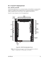
The Prototyping Board serves as a convenient interface for the LP3500, extending the IDC
headers to convenient screw-terminal connectors, and provides interfaces to the AC
adapter included with the Tool Kit and to a user-supplied external battery.
Figure B-2 shows the pinouts for the Prototyping Board.
Figure B-2. LP3500 Prototyping Board Pinout
NOTE:
The LP3500 must be plugged in to the Prototyping Board as described in
Chapter 2, “Getting Started,” for these signals to be available.
GND
VIN GND
VBA
T EXT
GND PWM2 PWM1 PWM0
GND
AIN7
AIN6
AIN5
AIN4
AIN3
AIN2
AIN1
AIN0 GND
IN15 IN14 IN13 IN12 IN11 IN10 IN09 IN08 IN07 IN06 IN05 IN04 IN03 IN02
IN01 IN00
J11
J12
J1
J2
J4
J6
J41
J42
J43
J44
J21
J23
External
Battery
Connection
Raw DC
Power
Input
Pushbutton
Switches
S1
S2
S3
S4
DS4 DS3 DS2 DS1
D1
PWR
R1
J3
3 V VBA
T
RS-232
PWM
Outputs
IN00
IN01
IN02
IN03
IN04
IN05
IN06
IN07
IN08
IN09
IN10
IN1
1
IN12
IN13
IN14
IN15
GND
RxE
TxE
GND
RxC/CTS
TxC/RTS
GND
RxB
TxB
GND
RS-485+
RS-485
GND
+K
OUT9
OUT8
OUT7
OUT6
OUT5
OUT4
OUT3
OUT2
OUT1
OUT0
K
Digital
Outputs
RS-485
GND
AIN0
AIN1
AIN2
AIN3
AIN4
AIN5
AIN6
AIN7
GND
PWM0
PWM1
PWM2
GND
VBAT EXT
GND
VIN
GND
Analog
Inputs
Power
Supply
Digital
Inputs
J5
J22
LEDs
Содержание Fox LP3500
Страница 1: ...Fox LP3500 C Programmable Single Board Computer User s Manual 019 0111 041029 E ...
Страница 6: ...Fox LP3500 ...
Страница 14: ...8 Fox LP3500 ...
Страница 22: ...16 Fox LP3500 ...
Страница 86: ...80 Fox LP3500 ...
Страница 120: ...114 Fox LP3500 ...
Страница 130: ...124 Fox LP3500 ...
Страница 134: ...128 Fox LP3500 ...
Страница 138: ...132 Fox LP3500 ...
Страница 142: ...136 Fox LP3500 ...
Страница 144: ......

