11
3.ASSEMBLING OF HOPPER
Insert Hopper Top Assembly I (52) into Hopper Bottom Assembly (3), align the holes. Make
sure hopper opens to the front (control side). Insert the Bolts (I) through the holes in the
Hopper and Kep Nuts (J), then open the Hopper Lid and tighten it from inside. The four sides
are installed in the same way.
4.POSITIONING THE CHAMBER ON THE BODY FRAME
Lift up the Chamber (1) on the Body Frame (4). Make sure that the Chamber (1) is inside the
left and right plate of the Frame (4). Align the Chamber holes with the plate holes and secure
with Bolt (B).
Содержание ZPG-700D
Страница 2: ......
Страница 4: ...2 SAVE THIS MANUAL FOR FUTURE REFERENCE...
Страница 10: ...8 ASSEMBLY INSTRUCTIONS PARTS DIAGRAM HOPPER BURNER ASSEMBLY...
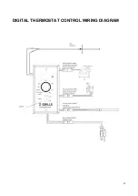
Страница 27: ...25 DIGITAL THERMOSTAT CONTROL WIRING DIAGRAM...


