YZ Systems DynaPak 2010FKNX Скачать руководство пользователя страница 35

DP-2010FKNX Version 09242003

YZ Systems, Inc. • 3101 Pollok Drive • Conroe, Texas • USA • 77303 • P: 936.788.5593 • F: 936.788.5720

35

Notes:

Содержание DynaPak 2010FKNX

Страница 1: ...DynaPak2010FKNX SystemSupport Manual Version 09242003...

Страница 2: ...sampling with the DPS 2 12 10 Sampler Set Up proportional to flow sampling 14 11 Sampler Maintenance 16 12 Trouble Shooting 20 13 Diagrams 1 DP 2000 pump assembled 24 2 DP 2000 pump exploded 25 3 YZ...

Страница 3: ...ns concerning installation operation contact your YZ representative or YZ Customer Service at 936 788 5593 2 System Components The primary components of the DynaPak 2010 Sampling System are illustrate...

Страница 4: ...l to flow sampling in this mode of operation the Z 65 counter operates as a dividing counter The Z 65 counter periodically energizes a low power solenoid valve As in the other two modes of operation t...

Страница 5: ...uld cause aerosols or significant pressure drops 4 2 The sampler should not be located within the defined meter tube region AGA 3 manual A The number of unobstructed straight pipe diameters upstream s...

Страница 6: ...as supply connection for the Filter Regulator located on the left side of the sampler enclosure CAUTION Incorrect operation of valves over tightening can result in damage to the valve components isola...

Страница 7: ...pressure supply valve without ensuring that the equalization valve is open Failure to do so may damage the DPS 2 s internal components d Open the other supply valve e Close the equalization valve f Ru...

Страница 8: ...lume constant pressure cylinder The free floating piston cylinder DuraSite may be installed in a horizontal position on an optional vessel rack Free floating piston cylinders should NOT be installed o...

Страница 9: ...stroke 7 4 Move all of the mode switches on the Z 65 to their off positions 7 5 Move both timer counter dials to the 0 position 00 minutes 7 6 Move mode switches 1 2 and 3 to the on position The pump...

Страница 10: ...E The time 18 minutes above corresponds to the dial setting shown for the Z65 model with the timer range setting in the factory position jumper on the two left pins See section 12 4 Timer Range Settin...

Страница 11: ...8 6 Turn mode switch 3 to on 8 7 Turn mode switch 4 to off 8 8 Press the test button once to initiate the timer sequence 8 3 Adjust the pump volume adjustment knob to the value used in the calculatio...

Страница 12: ...18 minutes above corresponds to the dial setting shown for the Z65 model with the timer range setting in the factory position jumper on the two left pins See section 12 4 Timer Range Setting 3 2 0 9...

Страница 13: ...6 Turn mode switch 3 to off 9 7 Turn mode switch 4 to off 9 8 Press the test button once to initiate the timer sequence NOTE For the Z 65 to operate the DP 2010 System a minimum pressure differential...

Страница 14: ...incoming connections to the Z 65 terminal strip see illustration b Turn mode switch 1 to on c Turn mode switch 2 to off d Turn mode switch 3 to on e Turn mode switch 4 to off OR 10 3 If the input is...

Страница 15: ...er of pulses you want to count before the sample pump strokes Example 20 pulses turn dials to 20 Press the test button once to load the value into the memory NOTE If the calculated counter setting is...

Страница 16: ...ample discharge 1 8 stainless steel tubing from the pump body d Screw the stroke adjustment knob all the way down to the 0 cc stroke setting e Unscrew the pump body by hand from the inlet check valve...

Страница 17: ...rings and bushings to prevent damage j Install the body bushing into the bottom of the pump body NOTE Apply a light coat of assembly grease on the plunger shaft prior to installation k Insert all oth...

Страница 18: ...te if the battery is low NOTE The solenoid must be connected to test the battery condition Battery condition cannot be tested with a volt meter Replacing a Depleted Battery 1 Remove the four thumb scr...

Страница 19: ...the DynaPak 2000 Series gas samplers Part Number Description Qty Location C4 0004 Filter element 1 see diagrams 3 and 4 D3 0002K DP 2000 pump seal kit 1 see diagrams 1 and 2 D3 0003 YZ filter regulat...

Страница 20: ...the DPS is sensing flow in the pipeline the green LED should illuminate If flow is not present the red LED should illuminate 12 3 LCD Stroke Indicator Test Mode A To test the stroke counter set the m...

Страница 21: ...he factory position far left position 12 4 Timer Range Setting A There are two Z 65 models the Z 65 6 1 and Z 65 6 03 Each Z 65 timer has two ranges for the timer setting dials 1 Z 65 6 1 Range Settin...

Страница 22: ...g b xx minutes set the configuration jumper to the center position Note To obtain maximum battery life choose the longest solenoid stroke rate possible WVWCN 5 UVGO 4463 CEVQT factory positioned for 1...

Страница 23: ...green LED will turn on and off and the red LED will illuminate again This will normally occur very quickly and give the appearance that the green LED blinks on when the pulse input is received and re...

Страница 24: ...eck Valve Spring Guide Inlet Check Valve Spring O Ring 006 P N A5 1006 O Ring 012 P N A5 1108 O Ring 108 P N B1 0014 Male Connector 1 8 P X 1 8 T P N B1 0015 Pump Body P N B1 0011 Spring Retainer Plun...

Страница 25: ...30 Set Screw P N C0 0096 P N C0 0014 Cap Screw 6 Each O Ring 012 P N B1 0020 P N C0 0026 Inlet Screen P N C4 0006 P N C3 0008 P N C4 0022 20 Micron Filter Inlet Check Valve Spring Inlet Check Valve Sp...

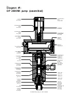
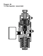
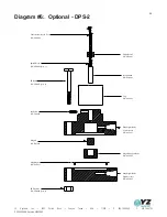
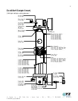
Страница 26: ...26 Diagram 3 YZ filter regulator assembled...

Страница 27: ...0073 O Ring 012 Retaining Nut P N A5 1012 Seat P N A3 0072 Upper Dart P N A3 0071 Upper Spring P N C3 0010 P N A3 0070 Piston P N A3 0069 Piston Spring Spring Cap P N A3 0068 P N A3 0067 Bonnet Pneuma...

Страница 28: ...Steel Set Screw Inlet Rupture Disc 1800 psi P N A3 0083 Rupture Disc Retainer P N A3 0084 YZ Valve Body P N A3 0137 0 1000 PSI LinkPlus Model No C1 0005 0 2000 PSI LinkPlus Model No C1 0006 0 600 PSI...

Страница 29: ...005 Set Screw P N E0 5001 Magnet Diaphragm SS Hex Nut P N C0 0048 Qty 8 P N A6 0013 P N G2 0002 Cable Assembly 30 Ft Shrink Wrap SS Bolt P N C0 0047 Qty 8 P N H2 0002 Qty 2 Magnet Support Body Diaphra...

Страница 30: ...65 6 Controller Assembly 1 1 Model Z 65 6 1 F2 0001 Model Z 65 6 03 F2 0018 2 Battery Pack E3 2001 1 3 Stroke Counter Assembly G1 0001 1 4 Terminal Strip 6 Position H1 0001 1 5 BCD Switch E1 0001 2 6...

Страница 31: ...ersion 09242003 YZ Systems Inc 3101 Pollok Drive Conroe Texas USA 77303 P 936 788 5593 F 936 788 5720 31 Diagram 8 Z 65 Installation Notes Wiring Control Documentation System Installation Notes and Re...

Страница 32: ...the pre charge gas too fast 2d When the cylinder becomes a maximum of 80 full see volume indicator all valves should be closed The product connection is slowly broken in order to vent any trapped pro...

Страница 33: ...YZ UniValve Purge Valve Nut P N A3 0080 P N A3 0063 Valve Seat P N C6 1003 Ser 4608 P N 12 1006 Ser 0321 and Prior P N 12 1007 Ser 0322 0613 P N 12 1008 Ser 0614 4087 P N C6 1002 Ser 4088 Piston Wash...

Страница 34: ...34 Notes...

Страница 35: ...DP 2010FKNX Version 09242003 YZ Systems Inc 3101 Pollok Drive Conroe Texas USA 77303 P 936 788 5593 F 936 788 5720 35 Notes...

Страница 36: ...ility and fitness for a particular purpose with respect to the product This limited warranty gives you specific legal rights You may have others which vary from state to state These remedies are not a...

Отзывы: