background image


1. SUMMARY 

1.1  Main Features 

  Adopt digital calibration technology for input measurement with non-linear calibration tables for standard 

thermocouples and RTDs are available in the instrument. 

  Adopt advanced AI artificial intelligence control algorithm, no overshoot and with the function  of auto 

tuning and self-adaptation. 

  Adopt advanced modular structure, with large numbers of output options. Easy installation to shorten 

the assembly time in manufacturing line. Maintenance of instruments make easy. 

  Friendly and customized operating interface leads to easy learning and simple manipulation.  Any 

parameter can be promoted to immediate operator access in Field Parameter Table or password 

protected in Full Parameter Table. 

  With universal power supply of 100-240VAC or 24VDC and various options of installation dimensions. 


ISO9001 (2000Version),high reliability of quality. 


CE certified, complying with EMC requirement, achieving world class level of quality, 

anti-interference ability and safety. 

POINTS FOR ATTENTION


  This manual introduces AI-518/518P model ARTIFICIAL INTELLIGENCE INDUSTRIAL CONTROLLER 

of Version 7.1. Certain functions may  not applicable for other versions.  After powering  on, the 

instrument model and software version will be shown.    User should pay attention to the version number.  

Please read this manual carefully to ensure proper and safe operation. 

  Please correctly set parameters according to input / output specification and function.    Only correctly 

wired instruments with parameters correctly set should be put into use. 

  Compared to Version 6.X  or earlier versions, some important changes are: New rear terminal 

layout,Heating/refrigerating dual output function, and both outputs can be either current or time 

proportional output. Alarm applies single lateral deadband; Support up to 4 channels of alarm or event 

outputs;  Compared with V7.0, AI-518P has 30segments ramps and soaks with dual editable event 

output. Adopted advanced X3/X5 high accuracy current output modules instead of X/X4, it makes 

higher transmittion output accuracy. 

1.2  Ordering Code Definition 

Advanced modularized hardware design is utilized for AI series instruments.  There are maximum five 

module sockets: multi-function input/output (MIO), main output (OUTP), alarm (ALM), auxiliary output (AUX) 

and communication  (COMM).  The input specification can be selected as  thermocouple, RTD, or linear 

current/voltage.   

The ordering code of AI-708/708P/808/808P series instrument is made up of 8 parts.  For example: 


AI-518  A 

  N    X3    L5   N    S4 —    F2    -- 24VDC 


It shows that the model of this instrument is AI-518, front panel dimension is 96

×

96mm, no module is 

installed in MIO (Multi-function I/O) socket, X3 linear current output module is installed in OUTP (main 

output), ALM (alarm) is L5  (dual relay contact output module), no module is installed in AUX (auxiliary 

output), a RS485 communication interface with photoelectric isolation is installed. It has external expanded 

input F2(radiant high thermometer), and the power supply of the instrument is 24VDC.Below is all 10 

Содержание AI Series

Страница 1: ...AI SERIES ARTIFICIAL INTELLIGENCE INDUSTRIAL CONTROLLER AI 518 518P Operation Instruction Ver 7 1...

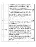
Страница 2: ...4 4 1 Setup program 11 4 4 2 Run Hold 11 4 4 3 StoP 11 4 4 4 Display and modify the running StEP 11 5 PARAMETERS AND SETTINGS 12 5 1 THE FULL PARAMETER TABLE 12 5 2 ADDITIONAL REMARKS OF SPECIAL FUNC...

Страница 3: ...ing to input output specification and function Only correctly wired instruments with parameters correctly set should be put into use Compared to Version 6 X or earlier versions some important changes...

Страница 4: ...slot ALM can add in L2 L4 W1 W2 G K1 V U Stands for auxiliary output AUX can add L2 L4 W1 W2 G K1 K3 X3 X5 V U I2 stands for communication COMM can add S S4 V U stands for expanded indexing table AI...

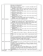
Страница 5: ...trigger If add I2 moudle AI 518P will be albe to on off control programming With K3 it s able to give three phase SCR contact zero crossing control output Main output OUTP commonly used as control ou...

Страница 6: ...zero crossing conduction It can replace the relay contact switch Compared to the relay contact output module W1 and W2 have longer life and lower interference They can largely lower the interference s...

Страница 7: ...uous 2A 20mS instantaneous repeat period 5s SSR Voltage output 12VDC 30mA used to drive SSR Thyristor zero crossing trigger output can trigger TRIAC of 5 500A a pair of inverse paralleled SCRs or SCR...

Страница 8: ...ignal can be inputted from terminals 14 and 15 and 2 wire transmitter can be inputted from terminals 16 and 14 Note 3 The compensation wires for different kinds of thermocouple are different and shoul...

Страница 9: ...e for module K1 K3 K5 and K6 Load Thyristor trigger output 100 380VAC IN4001 1N4001 Load Thyristor trigger output SCR X2 5 500A BX BX Capacitor Resistor Absorber Circuit Varistor G1 G2 G1 G2 ZNR ZNR V...

Страница 10: ...dition for AI 518P MIO OP1 OP2 AL1 AL2 AU1 AU2 are for input and output COM is for communication like PC 4 1 Display Status Note Not all models have the above display status When powered on the unit i...

Страница 11: ...cates that the external power is on and the brightness of OP1 shows the magnitude of phase shifting trigger output 4 2 Operation Description 4 2 1 Display status switch Depending on the instrument mod...

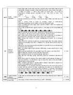
Страница 12: ...and waveform are analyzed to calculate optimum control parameters The auto tuning for AI series instrument will gratify for 90 users Due to the complexity of the automatic process parameters calculate...

Страница 13: ...but the timer stop working and the running time and setpoint remains At Hold status press and hold the key for about 2 seconds until the lower display window displays the Run symbol the instrument the...

Страница 14: ...hen PV 798C alarms is cancelled E g Set SV 700c dF 2 0C for heating 1 in run status when PV 700C it breaks 2 in stop status when PV 698C it reheats For on off control mode the hgiher dF the longer per...

Страница 15: ...e 1 each second then P 1000 10 100 If CtrL 4 then P parameter will be configured by increasing 10 times Ex P should be set to 1000 in the above example 1 9999 seconds t Lag time parameter Parameter t...

Страница 16: ...te 1 For thermocouples or RTD input only 0 or 0 0 is selectable and the internal resolution is 0 1 dIP only affect the display and has no affect to the accuracy of measurement or control 0 3 dIL Signa...

Страница 17: ...OP1 B 2 0 20mA linear current output Linear current output module should be installed to main output OP1 B 3 spare OP1 B 4 4 20mA linear current output Linear current output module should be installed...

Страница 18: ...splays the program step C 1 it displays PV measurement value only for AI 518P C 0 When the instrument work within HIAL LoAL C 1 SV is not litmited only for AI 518 not for AI 518P D 0 no remote setpoin...

Страница 19: ...Among which A is used to select 5 kinds of power cut event handling modes D is used to select 4 kinds of run modify event handling modes A 0 start to run the program from step 1 unless the instrument...

Страница 20: ...m and StEP value Note that 808 is the password of all AI series instrument In application the instrument should be set to other values to protect from modifications of parameters Meanwhile the managem...

Страница 21: ...ion is satisfied again the alarm will work Similarly in a direct action control system the absolute and deviation high limit alarms are blocked 5 2 5 Sectional power restriction CF E 1 With regards to...

Страница 22: ...tion AI 518 is adviced Install W1 OR L2 L4 in OUTP So that to achieve the best control result On off control can be decided by dF parameter AI controllers are needed to be set as CtrL 0 oP1 0 CF A can...

Страница 23: ...re controller is used in the application where the setpoint should be changed automatically with the time It provides 30 segment program control which can be set in any slope and the function of jump...

Страница 24: ...of curve fitting the instrument will smooth the turning point of the linear heating up cooling down and constant temperature curves automatically The degree of the smooth is relevant with the system...

Страница 25: ...7 2 1 Time setup txx 1 9999 min setting time of No xx StEP txx 0 the program is hold on StEP xx txx 1 30 negative value of time represents an operation command such as run Hold stoP jump and even out...

Страница 26: ...setting step 1 as jump segment For example There are three curves with the length of 3 steps represent three groups of process parameter they are separately arranged on StEP2 StEP4 StEP5 StEP7 StEP8 S...

Отзывы: