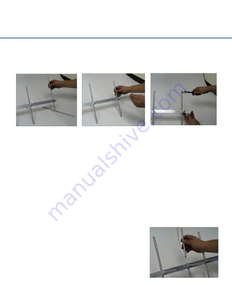
The Yagi elements are installed in pairs using a cam-lock mechanism to rigidly lock each element in place.
Each pair consists of one element with an eccentric cam and the second with a small round notch in the
center. Follow steps 1 thru 3 to install the three 13-1/4” long director pairs and the 14-3/4” long reflectpr pair.
4
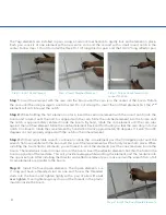
Step 1: Insert Cam Element
Step 2:Insert Notched Element
Step 3: Rotate Cam Element Into
Locked Position
Step 1
: Insert the element with the cam into the boom until the cam is in the center of the boom. Rotate
the cam until the side passage is unobstructed. Do not attempt to insert the notched element first, the 2
nd
element will not slide past the notch.
Step 2
: While holding the first element in place, insert the second element (with the round notch) into the
boom and rotate it until the notch is aligned with the cam. Slide the notched element into the boom until
the notch is approximately centered inside the boom. By hand, rotate the cam element until the cam rubs
against the notched element. Slide the notched element back and forth until you feel the cam drop into the
notch. Continue to rotate the cam element by hand until it turns approximately 30 degrees. If it won’t turn 30
degrees it is not properly aligned with the notch in the other element.
Step 3
: With an adjustable wrench, continue to rotate the cam element past the 30 degree point until the
wrench flats are parallel with the boom. At this point the two elements will be firmly locked into place. When
installing the two reflector elements, you will need to work the elements past the coax leadwire inside the
boom. The leadwire is routed in one corner of the boom. Insert the reflector elements first thru the hole in the
boom opposite of the leadwire. This will provide leverage while working the element past the leadwire into
the opposite hole. After installing the director and reflector element pairs, make certain the wrench flats of all
4 cam elements are parallel to the boom.
Step 4:
Install the four dipole elements. The dipole elements are
7: long and have a threaded stud on one end. Screw the threaded
studs into the boom and tighten lightly with a pair of pliers.
Do not
over tighten
. Over tightening may strip out the threads in the plastic
insulator inside the boom.
Step 4: Install The Four Dipole Elements


