


KZ55
Position actuator
user's manual
一 Overview
The engine intake control valve is a combination of a
corner motor and a disk valve with a corresponding diameter,
referred to as a position control valve. This position control
valve is used together with OT3120 controller or other standard
position signals produced by the company. It can realize
open-loop and closed-loop control, and is often used for gas
engine speed control or air-fuel ratio control.
The main function of the position control valve is to
convert the position signal output by the controller into the
specified corner position. The input of the angle motor is an
electrical signal, and the output is a mechanical rotation. The
amount of mechanical rotation (rotation angle) is proportional
to the input signal.
The corner motor needs a DC drive from the controller 0V
to 20V. The drive should be able to provide a maximum
continuous current of 4A and a peak current of 10A for 30
seconds.
It is the controller, not the corner motor, that controls the
stability and dynamic response of the engine. Therefore, the
engine should be adjusted according to the instructions of the
controller.
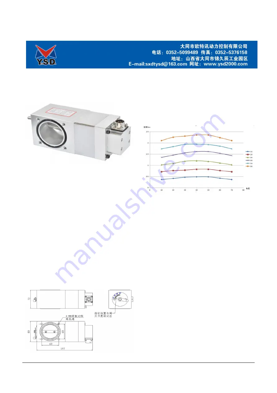
The dimensions and installation structure dimensions of
KZ55 position control valve are as follows
Figure 1-1 KZ55 Outline drawing of position control valve
According to the diameter of the valve disc, the position
control valve of KZ series products has multiple models, KZ55
is one of them. The rotation direction of the position control
valve: facing the pointer direction, the clockwise rotation
direction is the same as the direction of increasing fuel by the
engine fuel supply system, that is: turning clockwise to increase
the amount of fuel supplied to the engine, and rotating
counterclockwise to decrease the amount of fuel supplied to the
engine.
图
1-2 KZ55 Performance graph
The torque of KZ55 actuator is proportional to the current.
According to the actual use requirements and the prevention of
too much power and excessive temperature, which affects the
life of the product, the maximum continuous input current of
the controller is limited to 4A.
二 Principle description
2.1 Introduction
The speed controller sends a pulse-width-modulated PWM
signal to the angle motor by calculating the engine speed signal,
the position feedback signal and current signal of the angle
motor.
2.2 Corner motor
The rotation angle range of the rotation angle motor is 75 °
(DEG), within which the fuel supply mechanism of the engine
is controlled. The corner motor can output torque in both
directions (forward and reverse). The torque is proportional to
the current provided by the drive.
Corner motors use sealed bearings and are therefore
maintenance-free. The angular position sensor is installed at the
end of the rotor shaft and is electrically isolated from the drive
current circuit and the body.
The valve disc is mounted on the output shaft, and the
valve disc opens and closes as the angle motor moves.