


INSERT
THERMISTOR HARNESS
PHOTO HERE
INSERT
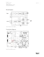
ICE MODULE
PHOTO HERE.
V04
M1507
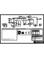
SET JUMPER P200 TO "115V" FOR NA.
SET IT TO "230V" FOR CE.
SEE LAYOUT DIAGRAM
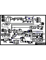
PRODUCTION NOTES
1 - Add RTV to C6 and R233.
2 - R29, R31, R43, R45, R46, R47 and R48 are used to
level up their respective pots during wave soldering.
3 - Please break the panel before testing.
4 - Break the connection of XLR J4 as per diagram.
5 - Do not forget to add the 2-pin header
to the thermistor harness assembly
as shown below:
MAINS VOLTAGE INPUT SETTING (NA<->CE)
Remove this
piece.
Break this
connection here.
Содержание SB110
Страница 12: ...BlankSize 12000x9000 INTO WAVE ...
Страница 22: ...ClinchRepeats X1 0 000Y3 2 800 BlankSize 14250x9000 0 INTO WAVE ...


