YORKVILLE Professional AP4020 Скачать руководство пользователя страница 6

550 Granite Court, Pickering, Ontartio CANADA L1W-3Y8

4625 Witmer Industrial Estate, Niagara Falls, New York USA 14305

SERVICE MANUAL

4

Yorkville Sound • http://www.yorkville.com

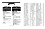
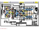
NOTE: Every time you replace blown output transistors on a 

M1126 board test the DC protection triac with the following circuit.

Conditions of test:

A) Pass a 100Hz 25v peak signal through the M1126 board under test with no load
connected to the amplifier output.

B) Connect points 1 and 2 as shown in the diagram. The amplifier should go into pro-
tect mode as the triac (if working) shorted the output of the amplifier to ground, and
the amplifier goes into current limit.

C) Disconnect the triac test circuit and allow the amplifier to complete it’s protect cycle.

D) Reverse connections 1 to 2 and 2 to 1 and test again. The same results as in B)
should be observed if the triac is working.

Only test the triac for one protect cycle as

prolonged testing will heat the triac to a high temperature.

M

M1

11

12

27

7  S

SH

HU

UT

TD

DO

OW

WN

N  C

CIIR

RC

CU

UIIT

T,,  F

FA

AN

N  C

CO

ON

NT

TR

RO

OLL  C

CIIR

RC

CU

UIIT

T,,

a

an

nd

d  S

SO

OF

FT

T  T

TU

UR

RN

N  O

ON

N  C

CIIR

RC

CU

UIIT

T::

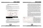
• The shutdown relay and its associated drive circuitry have two possible
operating states.
• Amplifier on under normal operating conditions.
• Amplifier power switch has just been turned OFF/ON, or the amplifier is in current
limit protecting the amplifier’s output transistors, or the amplifier has overheated.

Shutdown Circuit

Here is how the circuit accomplishes these functions. The relay’s normally closed con-
tacts short the output of the voltage amplifiers to ground when the power switch is off.
When the power switch is turned on, the relay remains off (normally closed) for about
6 seconds. C203 charges to 35V and results in Q203 turning off allowing Q201 to turn
on. As Q201 turns on, it connects the negative terminal of the relay’s coil (Pin 16) to
ground energizing the relay and opening the normally closed contacts.

550 Granite Court, Pickering, Ontartio CANADA L1W-3Y8

4625 Witmer Industrial Estate, Niagara Falls, New York USA 14305

SERVICE MANUAL

Yorkville Sound • http://www.yorkville.com

If prolonged current limiting occurs on the amplifier’s output transistors then D204 or

D205 (depending on which channel is current limiting) will be forward biased turning on
Q202 (from its off state). Now +100VDC appears on the collector of Q202 and through
R210 and R211 turn on Q203 therefore turning off Q201 by shorting its base emitter
junction. Q201 turning off will turn the relay off and the normally closed contacts (off
state) will short the outputs of the voltage amplifiers to ground so as not to continuously
stress the amplifier’s output transistors. A cycle now occurs. With the voltage amplifiers
now disabled there is no signal driving the output transistors (Q13 to Q28).

The current limit circuit protecting the output transistors (Q13 to Q28) turns off and

D204 and/or D205 are not forward biased and Q202 turns off. Through Q203 and
Q201 the relay is turned back on and the voltage amplifiers are now active again, dri-
ving the output transistors. If current limiting still occurs, then the same cycle will occur.
If the cause of current limiting  (low impedance or short on the speaker output termi-
nals) has been removed, then the amplifier will continue to operate normally.

The third operation that the relay provides is “overheat shutdown”. If for some rea-

son the fan cannot keep the heatsinks in a safe operating temperature area then the
fan control circuit (on board M1127) will deliver through D207 a positive current to turn
Q203 on and turn Q201 off to turn off the relay and disable the voltage amplifiers.
When the fan has cooled down the temperature of the amplifier, then the signal
through D207 will disappear and the relay circuit will turn on the relay to resume nor-
mal operation. Anytime the relay is in the “protect” mode (due to the abnormal states)
then contact pin 4 of the relay will illuminate LD3 (the protect LED on the front panel).

Soft Turn On Circuit
To reduce the “inrush” current that flows through the line cord from the 120 VAC power
source (typical with large linear power supplies), a circuit provides a soft turn on func-
tion. When the power switch is turned on, the current that initially flows through the pri-
mary of the transformer must flow through SG201 and SG202. These are surgestors
that reduce the peak inrush current flow. After about 500 milliseconds a relay’s con-
tacts short across the surgestors so that they are not stressed by the current flowing
through them under normal operation. A circuit consisting of Q240, Q241, C215, and
the associated resistors provides the time delay for the turn on cycle of the relay. The
circuit is very similar to the shutdown time delay circuit. Refer to the section on the
shutdown circuit for a circuit description.
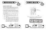
Fan Circuit

Looking at the schematic to board M1127, here is a
quick explanation of the fan control circuit. There is
a temperature sensor (AS35) on each M1126
board. When the amplifier is first turned on, Q207
and Q208 are off. The AS35 temperature sensors
are configured as temperature controlled current
sources. As either temperature sensor begins to
heat up, more current flows through D212 or D218
increasing the voltage drop across R235 or R236.
The hotter temperature sensor will provide more
current than the cooler sensor and therefore devel-
op a higher voltage across it’s associated 8K2
resistor. The higher voltage will forward bias D212
or D218 reverse biasing the cooler temperature

sensor’s diode so that the hotter sensor will control the fan speed. At 40 degrees C there

4

Содержание Professional AP4020

Страница 1: ...Schematic M1126 PCB layout 4 Service Kit M1146 m1126 5 Power Amp Module AP4020 U S A Yorkville Sound Inc 4625 Witmer Industrial Estate Niagara Falls New York 14305 USA Voice 716 297 2920 Fax 716 297 3689 WORLD HEADQUARTERS CANADA Yorkville Sound 550 Granite Court Pickering Ontario L1W 3Y8 CANADA Voice 905 837 8481 Fax 905 837 8746 Quality and Innovation Since 1963 Printed in Canada WEB www yorkvil...

Страница 2: ... 1 3821 HEYCO 1200 STRAIN RELIEF 1 4835 1 4W 56K 5 T R RES 4 6433 1N5257B 33V0 0W5 ZENER 5 T R 3 3638 12 CIR CABLE HOLDER 098 1 4836 1 4W 68K 5 T R RES 4 5101 BC550C TO92 NPN TRANS T R 14 3676 8 CIR CABLE HOLDER 098 2 4838 1 4W 100K 5 T R RES 2 5102 BC560C TO92 PNP TRANS T R 14 8701 4 40 KEPS NUT ZINC 20 6120 1 4W 100K 5 MINI T R RES 2 5103 MPSA06 TO92 NPN TRANS T R 3 8793 4 40 HEX NUT ZINC 3 4851...

Страница 3: ...iting the audio signal at U2 The charging attack and discharging release times of the limiter are 80mS and 3 5 seconds respectively Resistors R50 and R7 provide the charging path and resistor R51 provides the dis charge path The limiter can be defeated by placing the limiter switch S2 in the in position which disconnects Q5 and the charging discharging circuitry from V The activity LED circuit con...

Страница 4: ...ction of D19A D20A and D23A The signal at the junction of R61A and R62A drives the succeeding current amplifier Current Amplifier Section The current amplifier receives a high voltage audio signal from the voltage amplifier and provides the current drive necessary to drive speaker cabinets The current amplifier is a two tier complimentary output driver design controlled by a complimentary darlingt...

Страница 5: ...uced to about 6 volts measured dri ving an 8 ohm load Zener ZD8 protects the gate source junction of Q11 and also pro vides a supply current path through R29 for the floating battery NOTE The Power supply voltages given are those when the amplifier is not driving a speaker load This will allow yo to check the tier switching with the cover of the amplifi er off and the amplifier therefore running c...

Страница 6: ... occurs With the voltage amplifiers now disabled there is no signal driving the output transistors Q13 to Q28 The current limit circuit protecting the output transistors Q13 to Q28 turns off and D204 and or D205 are not forward biased and Q202 turns off Through Q203 and Q201 the relay is turned back on and the voltage amplifiers are now active again dri ving the output transistors If current limit...

Страница 7: ...n cables have been cut or pinched through their insulation If the fan is running at full speed at power up this usually indicates a problem with the fan circuitry on the M1127 board but it can also be caused by M1126 cir cuit problems A damaged AS35 temperature sensor located under the M1126 heatsinks can cause erratic fan behavior No output on either or both channels could be caused by intermitte...

Страница 8: ... R8 10K R7 3V0 1N5225B D1 GREEN R_ACTIVITY LD2 GREEN L_ACTIVITY LD1 220R R55A 8M2 R5 470K R4 470K R3 15v 220n C22 15v 220n C21 220p C2 220p C1 100K R2 100K R1 50V 100n C127 25V 100n C126 25V 47n C3 25V 47n C4 50V 330P C41 50V 330P C40 22K R43 1K2 R136 GRN LD4 RED LD3 PRTCT 18V GND 18V RCLIP LCLIP 10 9 8 7 6 5 4 3 2 1 DESCRIPTION OF CHANGE VER DATE MODEL S D D D D D D D APR 22 98 OCT 97 V V V V V V...

Страница 9: ...D PC 5736_TRACES_CHANGED_POT_SUPPORT CHANGED_FOR_PROTECT_CIRCUIT PC 5664_RIBBON_CABLE_CONNECTIONS FIRST_PRODUCTION AP 4020 M1128 PCB_DATABASE_HISTORY C40 330P R46 22K J9 J12 J1 14 PIN SOCKET C22 220n D2 4V7 P22 STYLE J4 C25 16V 33u C26 16V 33u D3 3V0 C39 330P Q2 A63 J10 LD8 6859 NSL 28AA C36 16v 22u Q4 BC560 Q5 BC560 Q6 BC560 C38 220p U2 33078P D9 4148 R43 22K J5 LD3 RED PROTECT LD6 RED L_CLIP J14...

Страница 10: ...K54 R11 9K760 R16 1K54 R13 10 9 8 7 6 5 4 3 2 1 DESCRIPTION OF CHANGE VER DATE MODEL S D D D D APR 22 98 DEC 02 97 D NOV 12 97 OCT 97 V V V V 2 10 2 00 V 2 00 1 00 N N N N SWITCH_FOR_BRPRTCT LVGND 28 PC 5694_ADD_CONNECTIONS_AT_BRIDGE CHANGED_C27 C28 C29 C30_TO_150N AND_MADE_VALUE_CHANGES_FOR_AP2020 REVERSED_INPUT_POLARITY FIRST_PRODUCTION AP4020 M1129 SCH_DATABASE_HISTORY 10K0 R37 10K0 R38 9K760 R...

Страница 11: ... 5 4 3 2 1 DESCRIPTION OF CHANGE VER DATE MODEL S D D D JUL 01 98 APR 16 98 DEC 02 97 D D NOV 97 OCT 97 V V V 4 00 3 00 2 00 V V 2 00 1 00 N N N ISOLATE_PIN_OF_SWITCH_S3 TO_BRIDGE_SWITCH PC 5694_PINS_10 12_OF_MC2_CONNECTED CHANGE_C27_C28_C29_C30_TO_150N SWAP_INPUTS_TO_BE_NONINVERTING RSPRE_WITH_LSPRE_AT_14PIN_CONNECTOR SWITCH_RREF_WITH_LREF_AND FIRST_PRODUCTION AP4020 4040 2020 VX1200 2400 2402 M1...

Страница 12: ... Q208 15AMPS A06 Q201 100u 25v C206 100u 25v C205 470U 63v C210 470U 63v C209 470U 63v C208 470U 63v C207 4v7 500mW ZD210 18V 500mW ZD208 18V 500mW ZD209 BC550 Q203 35AMP BR2 3 4 1 2 35AMP BR1 3 4 1 2 YSL 1300 120VAC 1KVA TYPE_H TR1 1M R237 4u7 63v C203 2N5401 Q202 MC33078 1 2 4 V 8V U201 6 5 7 MC33078 1 2 4 V 8V U201 2 3 1 7 8 9 10 3 2 6 5 4 1 33U 16V C201A 33U 16V C201B 16V 33U C202B 16V 33U C20...

Страница 13: ...01 CSA EY12 5R0 PART 6489 EY9 EY11 J7 V T R J29 J19 J18 J27 J15 J14 J24 J13 J8 J6 1 R214 0 5W 8K2 TP9 R238 200K V T R V T R V T R V T R V T R C216 100U 25V WC17B GREEN 11 10 9 8 7 6 5 4 3 2 1 DESCRIPTION OF CHANGE VER DATE MODEL S N N PC 5695_ADD_TP9 10_THICKEN_TRACKS 22K_ZD212 JUMPER_ZD210_6V2 4V7 V V 6 00 D D OCT 27 99 PC 5797_R235 R236_10K 8K2_ZD202_27K 5 10 JUL 15 98 MAR 27 98 JAN 21 98 DEC 12...

Страница 14: ...1 BP2 16v 500mW ZD7 MR854 D20 TP4 TP5 TP7 TP6 TP9 TP10 TP1 D9 TP8 18K R70 4uH L1 5R6 5W R63 3K3 R68A 47K R205 10u 120v BC550 Q20A BC560 Q21A 3K3 R69A 10K R67A 6800U 63V C22 6800U 63V C23 6800U 63V C24 FP 39R 16v 1W FP 1R 1W R49 FP 1R 1W R33 YS6910 Q21 YS6909 Q20 YS6910 Q28 YS6909 Q18 YS6910 Q26 YS6909 Q16 0R1 5W 0R1 5W YS6910 Q24 YS6909 Q14 YS6909 Q13 YS6909 Q19 YS6909 Q17 YS6909 Q15 YS6910 Q23 MR...

Страница 15: ... 2K R50A 4K7 R51A 1K5 1 HOLDER 3676 R53A 2K R43A 3K R56A 17K8 EY8 R58A 39R J12 R1 39R R62A 39R J25 C18A 22U 16V C19A 22U 16V 3894 Q15A MJE350 C26A 4U7 10V C22 5895 63V 6800u R73 2K R74 330R Q31 AS35 D14A 4148 D13A 4148 R40A 220R D16A 4148 D18A 4148 R46 1K J1 D19A 4148 D23A 4148 D22A 4148 Q14A BC560 Q17A BC550 J4 R61A 39R C29A 330U 16V Q12A 2N5551 Q13A 2N5401 R19 249R R83 200R R60A 150K 2W C27A 10u...

Страница 16: ...te for one s lack of electronic capability Before starting look at the board for repair and locate the version number It is very important that you follow the procedure for the appropriate circuit board version number A complimentary service manual for the AP4020 power amplifier is sup plied with this M1146KIT STEP 1 Locate the assembly drawing for the version number printed on the M1146 or M1126 ...

Страница 17: ... there is still a damaged part on the board instantly turn ing it on could blow up the board and you would be back where you started Connect the power wires and ground to the power supply Connect a digi tal multimeter to test pins 8 and 9 to measure the bias quiescent current and place a scope probe on the speaker output Be sure to turn the quies cent current trimpot RT1 fully counter clockwise No...

Страница 18: ...1146 KIT 1N5242B 1N5242B 6450 6450 M1146 KIT 6854 5113 5114 5260 5260 5102 5102 5102 5102 5102 5101 5101 5101 5101 5101 5101 6444 MAC224 4 4749 0R15 5 WATT 4749 0R15 5 WATT 4745 0R1 5 WATT 4745 0R1 5 WATT 4745 0R1 5 WATT 4745 0R1 5 WATT 6990 MJL3281A 6989 MJL1302A 6874 6873 MJE350 MJE340 4974 4973 4607 4607 4645 4645 6201 6201 6201 4911 4911 4804 4804 4973 4977 4977 4982 4982 4591 4593 4593 4606 4...

Страница 19: ... D5 350V 2N6517 Q7 2K2 R21 330R R74 2K R73 MT1 MT2 G TRIAC_MAC224 Q30 20K R35A 16v 10u C21 33K R64 10R R65 39R R32 39R R48 1R 0 5W R28 1R 0 5W R44 120v 220n C11 120v 220n C14 20K R40B 3R9 2W R62 150v 10n C19 BP1 BP2 16V 500mW ZD7 MR854 D20 TP4 TP5 TP7 TP6 TP9 TP10 TP1 D9 TP8 18K R70 4uH L1 5R6 5W R63 3 3K3 R68A 47K R205 10u 120v BC550 Q20A BC560 Q21A 3K3 R69A 10K R67A 4700U 80V C22 4700U 80V C23 4...

Страница 20: ...2A 4148 Q14A BC560 Q17A BC550 J4 R61A 47R C29A 330U 16V Q12A MPSA42 Q13A MPSA92 U2 4N35 R83 200R R60A 220K 2W C27A 10u 160V C28A 160V 10u Q18A MJE340 Q19A MJE350 C23A 500V 10P C22A 500V 10P TP5A D21A 4148 J26 HS2 3894 HS1 3894 EY8 EY7 EY4 1 1 2 2 JB2 EY6 C31 22N R34 270R JZD3 R17 249R J5 R57A 150R C30A 33u 16V R72A 33R R53A 2K C31A 33u 16V EY1 R45A 3K6 5WATT J34 1 1 2 2 JB3 R12 39R J19 R55A 21K5 R...

Страница 21: ...M1127 5 00 R E D G R EY G R EY AP4020CE AC WIRING OCT 24 2000 GREEN YELLOW 1196E 680n N L 4 17 17 15 17 WHITE BLACK GREY YELLOW RED RED GREY SHOWN WIRED FOR 230V BROWN BLACK BROWN BLUE ...

Страница 22: ...M1127 5 00 R E D G R EY G R EY AP4020CE AC WIRING OCT 24 2000 GREEN YELLOW 1196E 680n N L 4 17 17 15 17 WHITE BLACK GREY YELLOW RED RED GREY SHOWN WIRED FOR 245V BROWN BLACK BLUE BROWN ...

Отзывы: