


V03
M1449
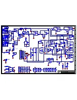
SEE LAYOUT DIAGRAM
PRODUCTION NOTES
1. RTV must be applied to the following caps: C22,C23,C24,C25,C26,C28,C36,C37,C50.
2. Apply RTV between C22 and C23 as well as between C24 and C25.
3. RTV must be applied to inductor L1.
4. Apply RTV between C53 and R102 and
bend C53 over R102 as in picture.
5. Place U10 and U12 aligned on the SIL pad.
No shorts to the heatsink are allowed.
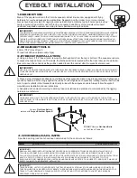
6. Mount the TO-220 retaining spring as per the diagram below:
NOTE: NUT IS ON TOP!
Outer heatsink
TO220 parts
8841
8581
PCB
8833 screw
Inner heatsink
4022 - Sil pad
3977 - Yellow spring