JOHNSON CONTROLS
21
SECTION 1 – INSTALLATION
FORM 160.81-NOM1
ISSUE DATE: 10/3/2020
1
When more than one unit is involved, the
major parts of each unit will be marked
to prevent mixing of assemblies. (Piping
and Wiring Drawings to be furnished by
Johnson Controls.)
All openings on compressor, oil separator and shells
are closed and charged with dry nitrogen [5 psig (34
kPa)].
Miscellaneous packaging of control center, oil eductor
filter, tubing, wiring, oil, isolators, solid state starter
(option), and other miscellaneous items are shipped
concurrently in a separate box. R-134a charge is
shipped concurrently or separately in 50 lb. and 125 lb
(23 and 57 kg) cylinders.
FORM 8 –
Shipped as two major assemblies. Unit first
factory assembled, refrigerant piped, wired and leak
tested; then dismantled for ship ment. Oil separator and
discharge line is skidded.
All wiring integral with hermetic compressor is left
on it, and all conduit is left on the shell. All openings
on compressor, oil separator and shells are closed and
charged with dry nitrogen (2 to 3 PSIG).
Units shipped dismantled MUST be reas-
sembled by, or under the supervision of a
Johnson Controls Representative.
INSPECTION – DAMAGE – SHORTAGE
The unit shipment should be checked on arrival to see
that all major pieces, boxes and crates are received.
Each unit should be checked on the trailer or rail car
when received, before unloading, for any visible signs
of damage. Any damage or signs of possible damage
must be reported to the transportation company imme-
diately for their inspection.
When received at the job site, all containers should be
opened and contents checked against the packing list.
Any material shortage should be reported to Johnson
Controls immediately.
JOHNSON CONTROLS WILL NOT BE RESPON-
SIBLE FOR ANY DAMAGE IN SHIPMENT OR AT
JOB SITE OR LOSS OF PARTS. (Refer to
Shipping
Damage Claims (Form 50.15‑NM)
.)
DATA PLATE
A unit data plate is mounted on the control center as-
sembly of each unit, giving unit model number, design
working pressure, water passes, refrigerant charge, se-
rial numbers, and motor power characteristics and con-
nection diagrams.
RE-ASSEMBLY
The following are step-by-step procedures to be used
to assemble the units. Refer to other sections in this
manual for further instruction.
Form 3 Shipment
1. Assemble vibration isolators to the unit. (Refer
to
Locating and Installing Isolator Pads on page
2. Level shells in both directions. The longitudi-
nal alignment of the shell should be checked by
placing a level on the top of the shell, next to the
discharge connection. The transverse alignment
should be checked by placing a level on the tops
of both end sheets. After shell is leveled, wedge
and shim each corner of the shell to solidly sup-
port it while assembling the other parts.
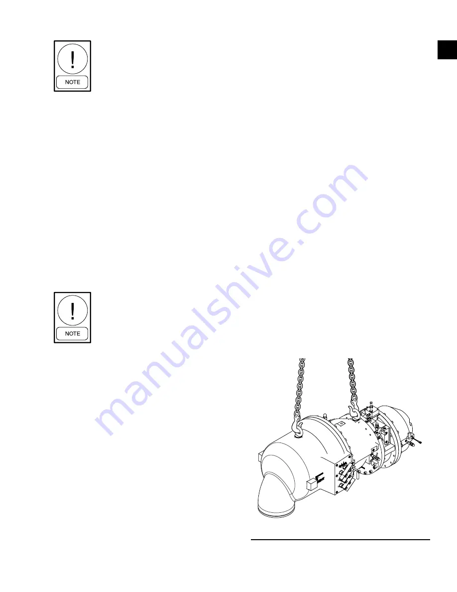
3. Lift compressor-motor assembly and remove pack-
ing materials and shipping skids. Keep the com-
pressor unit supported by the hoist until all connec-
tions are finally made to the shell assembly. (Refer
to
move closure covers and be sure flanges are clean.
LD08914
FIGURE 8 -
RIGGING COMPRESSOR ASSEMBLY


