JOHNSON CONTROLS
19
Section 3 - Maintenance
Form 160.78-O1
Issue date: 05/19/2021
3
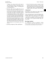
the shells. If a source of hot water is not readily
available, use a portable water heater.
Do not use
steam.
Connect a hose between the source of hot water
under pressure and the evaporator head drain con-
nection, out the evaporator vent connection, into
the condenser head drain, and out the condenser
vent. To avoid the possibility of causing leaks,
raise the temperature slowly so that the tubes and
shell are heated evenly.
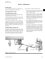
5. Close the system charging valve and the stop
valve between the vacuum indicator and the vac-
uum pump. Then disconnect the vacuum pump
leaving the vacuum indicator in place.
6. Hold the vacuum obtained in
Step 3
above in the
system for 8 hours; the slightest rise in pressure
indicates a leak or the presence of moisture, or
both. If after 24 hours the wet bulb temperature
in the vacuum indicator has not risen above 40°F
(4.4°C) or a pressure of 6.3 mm Hg, the system
may be considered tight.
Be sure the vacuum indicator is valved off
while holding the system vacuum and be
sure to open the valve between the vacuum
indicator and the system when checking
the vacuum after the 8 hour period.
7. If the vacuum does not hold for 8 hours within the
limits specified in
Step 6
, the leak must be found
and repaired.
Vacuum dehydration
To obtain a sufficiently dry system, use the following
procedure to evacuate and dehydrate a system in the
field. Although there are several methods of dehydrat-
ing a system, this method produces some of the best
results and provides accurate readings as to the extent
of dehydration.
The equipment required to follow this method of de-
hydration consists of a wet bulb indicator or vacuum
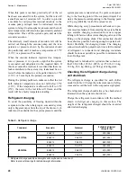
gauge, a chart showing the relation between dew point
temperature and pressure in inches of mercury in a
vacuum (see
), and a vacuum pump capable of
pumping a suitable vacuum on the system.
Operation
A refrigerant system can be dehydrated using this
method because the water present in the system reacts
to changes in a similar way that a refrigerant does.
By pulling down the pressure in the system to a point
where its saturation temperature is considerably be-
low room temperature, heat will flow from the room
through the walls of the system and vaporize the water,
allowing a large percentage of it to be removed by the
vacuum pump. The length of time necessary for the de-
hydration of a system depends on the size or volume of
the system, the capacity and efficiency of the vacuum
pump, the room temperature and the quantity of water
present in the system. By the use of the vacuum indi-
cator as suggested, the test tube will be evacuated to
the same pressure as the system, and the distilled water
will be maintained at the same saturation temperature
as any free water in the system, and this temperature
can be observed on the thermometer.
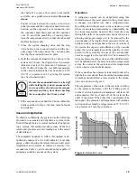
If the system has been pressure tested and found to be
tight before evacuation, then the saturation temperature
recordings should follow a curve similar to the satura-
tion curve shown in
.
The temperature of the water in the test tube will drop
as the pressure decreases, until the boiling point is
reached, at which point the temperature will level off
and remain at this level until all of the water in the
shell is vaporized. When this final vaporization has
taken place the pressure and temperature will continue
to drop until eventually a temperature of 35°F (1.6°C)
or a pressure of 5 mm Hg is reached.
LD00474
Figure 6 -
Saturation curve
Содержание YMC2 A
Страница 12: ...JOHNSON CONTROLS 12 Form 160 78 O1 Issue date 05 19 2021 THIS PAGE INTENTIONALLY LEFT BLANK ...
Страница 16: ...JOHNSON CONTROLS 16 Form 160 78 O1 Issue date 05 19 2021 THIS PAGE INTENTIONALLY LEFT BLANK ...
Страница 26: ...JOHNSON CONTROLS 26 Form 160 78 O1 Issue date 05 19 2021 THIS PAGE INTENTIONALLY LEFT BLANK ...

