FORM 201.26-NM1
ISSUE DATE: 1/19/2018
SECTION 4 – INSTALLATION
JOHNSON CONTROLS
36
WATER TREATMENT
The unit performance given in the Design Guide is
based on a fouling factor of 0.00025 ft
2
/hr °F/BTU
(0.44m
2
ºC/kW). Dirt, scale, grease and certain types
of water treatment will adversely affect the heat ex-
changer surfaces and therefore unit performance. For-
eign matter in the water system(s) can increase the heat
exchanger pressure drop, reducing the flow rate and
causing potential damage to the heat exchanger tubes.
Aerated, brackish or salt water is not recommended for
use in the water system(s). Johnson Controls recom-
mends that a water treatment specialist is consulted to
determine that the proposed water composition will not
affect the evaporator materials of carbon steel and cop-
per. The pH value of the water flowing through the heat
exchangers must be kept between 7 and 8.5.
Glycol Solutions
For unit operation with chilled liquid temperatures
leaving the cooler at below 40°F (4.4°C), glycol solu-
tions should be used to help prevent freezing. Section
9, gives recommended solution strength with water, as
a percentage by weight, for the most common types
of glycol. It is important to check glycol concentration
regularly to ensure adequate concentration and avoid
possible freeze-up in the cooler.
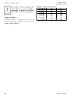
When using glycol solutions, pressure
drops are higher than with water. Special
care must be taken not to exceed the maxi-
mum pressure drop allowed.
OPTION FLANGES
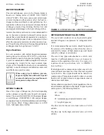
One of two types of flanges may be fitted depending
on the customer or local Pressure Vessel Code require-
ments. These are ANSI/AWWA C-606 adapter flanges
or weld flanges. ANSI/AWWA C-606 adapter flanges
are supplied loose for field installation and weld flang-
es are factory fitted. Flange dimensions are to ISO
7005 - NP10 (BS 4504 - NP10).
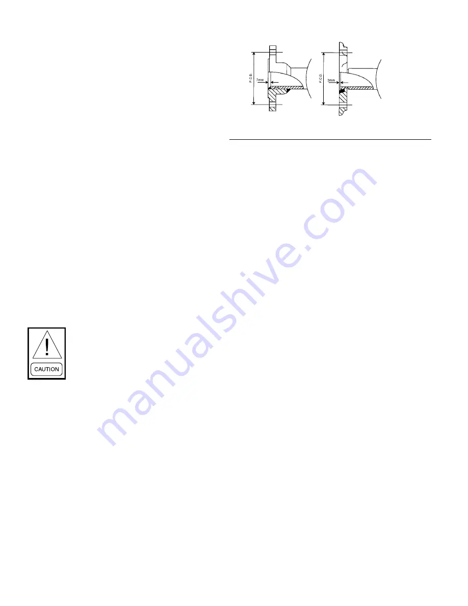
LD06602
FIGURE 9 -
ANSI/AWWA C-606 - ADAPTER FLANGES
REFRIGERANT RELIEF VALVE PIPING
The cooler and condenser are each protected against
internal refrigerant overpressure by refrigerant relief
valves.
It is recommended that each valve should be piped to
the exterior of the building so that when the valve is
activated the release of high pressure gas and liquid
cannot be a danger or cause injury.
The size of any pipework attached to a relief valve
must be of sufficient diameter so as not to cause re-
sistance to the operation of the valve.
For piping size
requirements and specifications, refer to ASHRE-15
(latest edition).
If relief pipework is common to more than one valve its
cross sectional area must be at least the total required
by each valve. Valve types should not be mixed on a
common pipe. Precautions should be taken to ensure
that the exit of relief valves/vent pipe remain clear of
obstructions at all times.
Unless otherwise specified by local regulations, the in-
ternal diameter depends on the length of pipe required
and is given by the following formula:
D
5
= 1.447 x L
Where:
D = minimum pipe internal diameter (cm)
L = length of pipe (m)
The flow rate for the low side relief valve is 26.8 lb
air/min.
The flow rate for the high side relief valve is 49.8 lb
air/min.
Содержание YCWL0056SE
Страница 4: ...FORM 201 26 NM1 ISSUE DATE 1 19 2018 JOHNSON CONTROLS 4 THIS PAGE INTENTIONALLY LEFT BLANK...
Страница 30: ...FORM 201 26 NM1 ISSUE DATE 1 19 2018 JOHNSON CONTROLS 30 THIS PAGE INTENTIONALLY LEFT BLANK...
Страница 146: ...FORM 201 26 NM1 ISSUE DATE 1 19 2018 JOHNSON CONTROLS 146 THIS PAGE INTENTIONALLY LEFT BLANK...
Страница 154: ...FORM 201 26 NM1 ISSUE DATE 1 19 2018 JOHNSON CONTROLS 154 THIS PAGE INTENTIONALLY LEFT BLANK...
Страница 168: ...FORM 201 26 NM1 ISSUE DATE 1 19 2018 JOHNSON CONTROLS 168 THIS PAGE INTENTIONALLY LEFT BLANK...
Страница 186: ...FORM 201 26 NM1 ISSUE DATE 1 19 2018 JOHNSON CONTROLS 186 NOTES...

