JOHNSON CONTROLS
195
SECTION 6 - TECHNICAL DATA
FORM 201.23-NM2
ISSUE DATE: 09/25/2020
6
DC Bus Voltage Isolation Board
LD10620
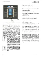
The DC Bus Isolation Board allows the VSD Logic
Board to read the voltage on the DC BUS without
exposing the VSD Logic Board to the high voltage.
Instead, the DC Bus Isolation Board contains a resis-
tor network that forms voltage dividers with resistors
on the VSD Logic Board, which steps down the volt-
ages so that scaled down voltages proportional to the
full and 1/2 bus voltages can be safely fed to the VSD
Logic Board. The DC Bus Isolation Board supplies 3
connections to the VSD Logic Board; plus bus, minus
bus and half bus.
Chiller Circuit Breaker
LD10623
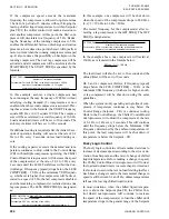
An Optional Circuit Breaker may be supplied on the
input of the system. The incoming power will be fed
to the terminals on the circuit breaker. If the Circuit
Breaker Option is not selected, incoming power will
be fed to terminal blocks. The breaker also provides
ground fault protection. 2 and 3 compressor chillers
utilize one circuit breaker, while 4 compressor chillers
utilize 2 breakers.
CHILLER CONFIGURATION JUMPERS
There are a number of chiller configuration jumpers
that are factory wired into wire harnesses or plugs.
These jumpers typically never need to be reviewed un-
less in some unlikely situation, a chiller is incorrectly
configured or a loose connection occurs.
Number of Compressors Configuration
Jumper
Software packs (EPROM’s) are common between
2, 3 and 4 compressor chillers. As a result, the VSD
Logic Board must be configured for the actual num-
ber of compressors. The chiller is configured for the
number compressors through the use of jumpers, fac-
tory plugged into the J1 plug on the VSD Logic Board.
This hard wiring configures the VSD Logic Board
for the number of compressors on the chiller, avoid-
ing mis-programming. The jumpers are only checked
at power-up. If no jumpers are sensed, or an invalid
combination is sensed and communicated to the Chill-
er Control Board, start-up of the unit will be inhibited
and an “INVALID NUMBER OF COMPRESSORS
SELECTED” warning message will be displayed in
the Status display.
shows the chiller number of
compressors and the associated location of the jumpers
to program the appropriate compressor configuration.
TABLE 3 -
COMPRESSORS AND THE
APPROPRIATE JUMPER POSITIONS
# OF
COMPRESSORS
VSD LOGIC BOARD
JUMPER POSITION
2
J1-10 to J1-9
3
J1-11 to J1-9
4
J1-12 to J1-9
Содержание YCIV Series
Страница 14: ...JOHNSON CONTROLS 14 FORM 201 23 NM2 ISSUE DATE 09 25 2020 THIS PAGE INTENTIONALLY LEFT BLANK...
Страница 32: ...JOHNSON CONTROLS 32 FORM 201 23 NM2 ISSUE DATE 09 25 2020 THIS PAGE INTENTIONALLY LEFT BLANK...
Страница 40: ...JOHNSON CONTROLS 40 FORM 201 23 NM2 ISSUE DATE 09 25 2020 THIS PAGE INTENTIONALLY LEFT BLANK...
Страница 50: ...JOHNSON CONTROLS 50 FORM 201 23 NM2 ISSUE DATE 09 25 2020 THIS PAGE INTENTIONALLY LEFT BLANK...
Страница 105: ...JOHNSON CONTROLS 105 SECTION 6 TECHNICAL DATA FORM 201 23 NM2 ISSUE DATE 09 25 2020 THIS PAGE INTENTIONALLY LEFT BLANK...
Страница 325: ...JOHNSON CONTROLS 325 FORM 201 23 NM2 ISSUE DATE 09 25 2020 NOTES...


