York R-134a Скачать руководство пользователя страница 7

JOHNSON CONTROLS

7

FORM 160.76-O1 

ISSUE DATE: 05/22/2019

1

The refrigerant vapor, which is produced by the boil-

ing action in the evaporator, flows to the compressor 

where the rotating impeller increases its pressure and 

temperature and discharges it into the condenser. Wa-

ter flowing through the condenser tubes absorbs heat 

from the refrigerant vapor, causing it to condense. The 

condenser water is supplied to the chiller from an ex-

ternal source, usually a cooling tower. The condensed 

refrigerant drains from the condenser into the liquid 

return line, where the variable orifice meters the flow 

of liquid refrigerant to the evaporator to complete the 

refrigerant circuit.
The major components of a chiller are selected to han-

dle the refrigerant, which would be evaporated at full 

load design conditions. However, most systems will 

be called upon to deliver full load capacity for only a 

relatively small part of the time the unit is in operation. 

CAPACITY CONTROL

The major components of a chiller are selected for full 

load capacities, therefore capacity must be controlled 

to maintain a constant chilled liquid temperature leav-

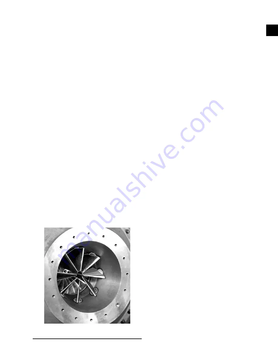
ing the evaporator. Pre-rotation vanes (PRV), located 

at the entrance to the compressor impeller, compensate 

for variation in load (See 

Figure 1

).

The position of these vanes is automatically controlled 

through a lever arm attached to an electric motor lo-

cated outside the compressor housing. The automatic 

adjustment of the vane position in effect provides the 

performance of many different compressors to match 

various load conditions from full load with vanes wide 

open to minimum load with vanes completely closed.

SECTION 1 - DESCRIPTION OF SYSTEM AND  

FUNDAMENTALS OF OPERATION

SYSTEM OPERATION DESCRIPTION 

The YORK Model YK Chiller is commonly applied 

to large air conditioning systems, but may be used 

on other applications. The chiller consists of an open 

motor mounted to a compressor (with integral speed 

increasing gears), condenser, evaporator and variable 

flow control.
The chiller is controlled by a modern state of the art 

Microcomputer Control Center that monitors its opera-

tion. The Control Center is programmed by the opera-

tor to suit job specifications. Automatic timed start-ups 

and shutdowns are also programmable to suit night-

time, weekends, and holidays. The operating status, 

temperatures, pressures, and other information perti-

nent to operation of the chiller are automatically dis-

played and read on a graphic display. Other displays 

can be observed by pressing the keys as labeled on the 

Control Center. The chiller with the OptiView Control 

Center is compatible with an electro-mechanical start-

er, YORK Solid State Starter (optional), or Variable 

Speed Drive (optional).
In operation, a liquid (water or brine to be chilled) 

flows through the evaporator, where boiling refrigerant 

absorbs heat from the liquid. The chilled liquid is then 

piped to fan coil units or other air conditioning terminal 

units, where it flows through finned coils, absorbing 

heat from the air. The warmed liquid is then returned to 

the chiller to complete the chilled liquid circuit.

7619A(D)

FIGURE 1 - 

COMPRESSOR PRE-ROTATION VANES

Содержание R-134a

Страница 1: ...TIVIEWTM CONTROL CENTER FOR ELECTRO MECHANICAL STARTER SOLID STATE STARTER AND VARIABLE SPEED DRIVE CENTRIFUGAL LIQUID CHILLERS OPERATIONS AND MAINTENANCE Supersedes 160 76 O1 1018 Form 160 76 O1 519 LD15222 Issue Date May 22 2019 035 27332 100 ...

Страница 2: ... this document and any referenced materials This in dividual shall also be familiar with and comply with all applicable industry and governmental standards and regulations pertaining to the task in question SAFETY SYMBOLS The following symbols are used in this document to alert the reader to specific situations Indicates a possible hazardous situation which will result in death or serious injury i...

Страница 3: ...us 160 76 PW6 Wiring Diagram Field Connections Model YK Chillers Style H Q3 Q7 with Low Voltage Variable Speed Drive 160 76 PW7 CHANGEABILITY OF THIS DOCUMENT In complying with Johnson Controls policy for con tinuous product improvement the information con tained in this document is subject to change without notice Johnson Controls makes no commitment to update or provide current information autom...

Страница 4: ... 05 22 2019 NOMENCLATURE YK 6A 6Q Q7 EM H MOTOR CODE POWER SUPPLY for 60 Hz 5 for 50 Hz COMPRESSOR CODE CONDENSER CODE EVAPORATOR CODE MODEL STYLE Design Level Refer to YK Engineering Guide for Form 160 76 EG1 Shell Motor Compressor combinations ...

Страница 5: ...e System 12 Prolonged Shutdown 12 SECTION 3 SYSTEM COMPONENTS DESCRIPTION 13 General 13 Compressor 13 Capacity Control 13 Compressor Lubrication System 13 Oil Pump 13 Oil Heater 17 Motor Driveline 17 Heat Exchangers 17 Refrigerant Flow Control 17 Optional Service Isolation Valves 18 Optional Hot Gas Bypass 18 Optiview Control Center 18 Solid State Starter Optional 18 Variable Speed Drive Optional ...

Страница 6: ...on Of Chiller 23 FIGURE 12 Saturation Curve 26 FIGURE 13 Diagram Megging Motor Windings 26 FIGURE 14 Motor Starter Temperature And Insulation Resistances 27 TABLE 1 Operation Analysis Chart 21 TABLE 2 System Pressures 24 TABLE 3 Guide to Motor Greasing and Shaft Rotation Intervals 32 TABLE 4 SI Metric Conversion 37 Vacuum Dehydration 25 Operation 25 Refrigerant Charging 26 Checking The Refrigerant...

Страница 7: ...ffect provides the performance of many different compressors to match various load conditions from full load with vanes wide open to minimum load with vanes completely closed SECTION 1 DESCRIPTION OF SYSTEM AND FUNDAMENTALS OF OPERATION SYSTEM OPERATION DESCRIPTION The YORK Model YK Chiller is commonly applied to large air conditioning systems but may be used on other applications The chiller cons...

Страница 8: ...sowers ext jci com 717 771 7535 YK Mod G Refrigerant Flow Thru Cross Section Diagram Falling Film Evaporator LEGEND High Pressure Vapor High Pressure Liquid Refrigerant Low Pressure Liquid Refrigerant Low Pressure Vapor COMPRESSOR EVAPORATOR DISCHARGE PRE ROTATION VANES SUCTION BAFFLE SUB COOLER LIQUID LEVEL CONDENSER LIQUID LEVEL VALVE HOT GAS BYPASS VALVE LIQUID LEVEL SUCTION OPTIONAL ISOLATION ...

Страница 9: ...P button When the user presses this button a dialog box is displayed instructing the user to press the ENTER button to stop the chiller or the CANCEL button to abort the stop command The Soft Stop command will drive the PRV closed and then shut off the chiller SECTION 2 SYSTEM OPERATING PROCEDURES OIL HEATERS If the oil heater is de energized during a shutdown pe riod it must be energized for 12 h...

Страница 10: ... chiller is designed to use less power by tak ing advantage of lower than design temperatures that are naturally produced by cooling towers throughout the operating year Exact control of condenser water such as a cooling tower bypass is not necessary for most installations The minimum entering condenser water temperature for full and part load conditions is specified in the chiller engineering gui...

Страница 11: ...he condenser saturation temperature based upon condenser pressure sensed by the condenser transducer on the SYSTEM Screen 6 Check the compressor discharge temperature on the SYSTEM Screen During normal operation discharge temperature should not exceed 220 F 104 C 7 Check the compressor motor current on the SYSTEM Screen 8 Check for any signs of dirty or fouled condenser tubes The temperature diffe...

Страница 12: ...iView panel or rapid stop with the COM PRESSOR STOP RESET switch The compressor will stop automatically The oil pump will contin ue to run for coastdown period The oil pump will then stop automatically 2 Stop the chilled water pump if not wired into the Microcomputer Control Center in which case it will shut off automatically simultaneously with the oil pump The actual water pump con tact operatio...

Страница 13: ... be supplied with forced lubrication as follows 1 Compressor Drive Shaft Low Speed a Shaft seal b Front and rear journal bearings one on each side of driving gear c Low speed thrust bearing forward and reverse 2 Compressor Driven Shaft High Speed a Forward and reverse high speed thrust bearing b Two journal bearings 3 Speed Increasing Gears a Meshing surfaces of drive and pinion gear teeth To prov...

Страница 14: ...E 05 22 2019 SECTION 3 SYSTEM COMPONENTS DESCRIPTION FRONT VIEW Figure 5 SYSTEM COMPONENTS FRONT VIEW VARIABLE SPEED DRIVE EVAPORATOR COMPRESSOR SUCTION RELIEF VALVES SIGHT GLASS VARIABLE SPEED OIL PUMP CONTROL BOX OPTIVIEW CONTROL CENTER LD15222 ...

Страница 15: ...5 SECTION 3 SYSTEM COMPONENTS DESCRIPTION FORM 160 76 O1 ISSUE DATE 05 22 2019 3 3 LD15223 Figure 6 SYSTEM COMPONENTS REAR VIEW DISCHARGE LINE COMPRESSOR OIL PUMP HOUSING LIQUID LINE REAR VIEW MOTOR OIL FILTER CONDENSER ...

Страница 16: ...GHT GLASSES OIL COOLER OIL TEMP CONTROL REFRIG THRUST COLLAR BEARING PRV INLET VALVES BEARING PINION GEAR SHAFT IMPELLER H S SHAFT SEAL LOW SPEED THRUST COVER LOW SPEED GEAR LOW SPEED GEAR REAR BEARING DOUBLE BELLOWS SHAFT SEAL HIGH SPEED THRUST COVER THRUST COLLAR MAIN JOURNAL AND THRUST BEARING HIGH PRESSURE TRANSDUCER EMERGENCY OIL RESERVE COMPRESSOR ROTOR SUPPORT SECTION OIL Figure 7 SCHEMATIC...

Страница 17: ... efficiency minimize refrigerant charge and maintain reliable control A specifically designed spray distribu tor provides uniform distribution of refrigerant over the entire length to yield optimum heat transfer The hybrid falling film evaporator design has suction baf fles around the sides and above the falling film section to prevent liquid refrigerant carryover into the com pressor A 1 1 2 in 3...

Страница 18: ...SS Hot gas bypass is optional and is used to eliminate compressor surge during light load or high head op eration The OptiView control panel will automati cally modulate the hot gas valve open and closed as required Adjustment of the hot gas control valve must be performed by a qualified service technician follow ing the Hot Gas Set up procedure Changes in chilled water flow will require re adjust...

Страница 19: ...rom the evaporator through the dehy drator to the compressor sump CHANGING THE DEHYDRATOR To change the dehydrator use the following procedure 1 Isolate the dehydrator at the stop valves 2 Remove the dehydrator See Figure 8 3 Assemble the new filter drier 4 Open evaporator stop valve and check dehydrator connections for refrigerant leaks 5 Open all the dehydrator stop valves OIL EDUCTOR BLOCK SOLE...

Страница 20: ...ainer of new oil and con nect the pump discharge connection to the oil charging valve A located on the remote oil res ervoir cover plate See Figure 9 Do not tighten the connection at the charging valve until after the air is forced out by pumping a few strokes of the oil pump This fills the lines with oil and prevents air from being pumped into the system 3 Open the oil charging valve and pump oil...

Страница 21: ...ifice problem Remove obstruction Temperature difference between leaving chilled water and refrigerant in the evaporator greater than normal with normal discharge temperature Evaporator tubes dirty or restricted Clean evaporator tubes Temperature of chilled water too low with low motor amperes Insufficient load for system capacity Check pre rotation vane motor operation and setting of low water tem...

Страница 22: ...y blocked oil supply inlet Check oil inlet for blockage 8 SYMPTOM OIL PRESSURE GRADUALLY DECREASES Noted by Observation of Daily Log Sheets When oil pump VSD frequency increases to 55 Hz to maintain target oil pressure Oil filter is dirty Change oil filter 9 SYMPTOM OIL PRESSURE SYSTEM CEASES TO RETURN AN OIL REFRIGERANT SAMPLE Oil refrigerant return not functioning Filter drier in oil return syst...

Страница 23: ...g And Repairs on page 28 CONDUCTING PRESSURE TEST With the refrigerant charge removed and all known leaks repaired the system should be charged with a small amount of refrigerant mixed with dry nitrogen so that electronic leak detector can be used to detect any leaks too small to be found by the soap test To test with refrigerant proceed as follows 1 With no pressure in the system charge refrigera...

Страница 24: ...improve evacuation circulate hot water not to exceed 125 F 51 7ºC through the evaporator and condenser tubes to thoroughly dehydrate the shells If a source of hot water is not readily avail able a portable water heater should be employed DO NOT USE STEAM A suggested method is to connect a hose between the source of hot water under pressure and the evaporator head drain con nection out the evaporat...

Страница 25: ...e capacity and efficiency of the vacuum pump the room temperature and the quantity of water present in the system By the use of the vacuum indi cator as suggested the test tube will be evacuated to the same pressure as the system and the distilled water will be maintained at the same saturation temperature as any free water in the system and this temperature can be observed on the thermometer If t...

Страница 26: ...g containers should be done as quickly as possible to minimize the loss of refrigerant Refrigerant may be furnished in cylinders containing either 30 50 125 1 025 or 1750 lb 13 6 22 6 56 6 464 or 794 kg of refrigerant The nameplate on the chiller contains the correct refrigerant charge information for the chiller CHECKING THE REFRIGERANT CHARGE DURING UNIT SHUTDOWN The refrigerant charge is specif...

Страница 27: ...the motor should not be run The motor should be heated to 250 F in an effort to remove moisture and obtain an acceptable reading at room ambient This can be done either by baking in a forced hot air oven or if proper voltage is available apply 5 10 of rated voltage to motor windings 4 A ny gradual or abrupt decrease in Megger readings over an extended period of time is an indication of deteriorati...

Страница 28: ...Areliable water treat ment company can be consulted to determine whether water treatment is necessary and if so to furnish the proper treatment for the particular water condition Cleaning Evaporator And Condenser Tubes Evaporator It is difficult to determine by any particular test wheth er possible lack of performance of the water evaporator is due to fouled tubes alone or due to a combination of ...

Страница 29: ...leak ing and water has entered the system the evaporator and condenser should be valved off from the rest of the water circuit and drained immediately to prevent severe rusting and corrosion The refrigerant system should then be drained and purged with dry nitrogen to prevent severe rusting and corrosion If a tube leak is indicated the exact location of the leak may be deter mined as follows 1 Rem...

Страница 30: ...he operation of the compressor Internal wearing of compressor parts could be a seri ous problem caused by improper lubrication brought about by restricted oil lines passages or dirty oil filters If the unit is shutting down on HOT High Oil Tem perature or Low Oil Pressure OP change the oil filter element Examine the oil filter element for the pres ence of aluminum particles Aluminum gas seal rings...

Страница 31: ...et oil pressure When the oil filter is changed it should be in spected thoroughly for any aluminum particles which would indicate possible bearing wear If aluminum particles are found this should be brought to the attention of the nearest Johnson Controls office for their further investigation and recommendations 2 Oil Changing The oil in the compressor must be changed annually or earlier if it be...

Страница 32: ... and lines must be cleaned of the old grease Follow all standard lookout tag out procedures prior to greasing motor After greasing motor at rest run motor for a minimum of 45 minutes before replacing plug if equipped Motor must be equipped with grease extensions on DE bearing for performance of this task Verify with motor nameplate any discrepancy before lubricating contact technical support for a...

Страница 33: ...calibrate 1 Form an open top cardboard cube 1 in x 1 in x 1 in 2 Pump grease into this container until the grease is level with the top counting the number of pumps 3 When the grease is level with the top this is the number of pumps for one cubic inch of grease 4 Multiply the number of pumps by 1 5 to get the number of pumps for YORK chiller motor bear ings Over greasing can be as detrimental as u...

Страница 34: ...y been compromised Procedure for WEG Motors Provided it is not more than six months old per its nameplate a WEG motor should be properly greased from the factory and ready to operate directly out of its crate without the need for additional lubrication After the number of operational run hours listed on the motor s nameplate for each bearing install the specified quantity of the recommended grease...

Страница 35: ...e temperature dif ference between the refrigerant and the chilled water increases slowly over the operating season it is an indication that the evaporator tubes may be fouling or that there may be a water bypass in the waterbox requiring gasket replacement or refrig erant may have leaked from the chiller 3 Heat recovery condenser tubes should be evalu ated similar to evaporator tubes when the heat...

Страница 36: ... if applicable X 2 Perform oil analysis on compressor lube oil 1 X Perform refrigeration analysis 1 X Perform vibration analysis X Clean tubes X 2 Perform Eddy current testing and inspect tubes 2 5 Years Lubricate motor Refer to motor manufacturer s recommendations For operating and maintenance requirements listed above refer to appropriate service literature or contact your local Johnson Controls...

Страница 37: ...Celsius multiply by 5 9 or 0 5556 Example 10 0 F range x 0 5556 5 6 C range Table 4 SI METRIC CONVERSION MEASUREMENT MULTIPLY ENGLISH UNIT BY FACTOR TO OBTAIN METRIC UNIT Capacity Tons Refrigerant Effect ton 3 516 Kilowatts kW Power Horsepower 0 7457 Kilowatts kW Flow Rate Gallons Minute gpm 0 0631 Liters Second l s Length Feet ft 0 3048 Meters m Inches in 25 4 Millimeters mm Weight Pounds lbs 0 4...

Страница 38: ...m Pennsylvania USA 17349 1 800 524 1330 Subject to change without notice Printed in USA Copyright by Johnson Controls 2019 www johnsoncontrols com ALL RIGHTS RESERVED Form 160 76 O1 519 Issue Date May 22 2019 Supersedes 160 76 O1 1018 ...

Отзывы: