036-21584-002 Rev. A (1205)
Unitary Products Group
3
* ESP (External Static Pressure) .5" WC is at furnace outlet ahead of cooling coil.
Annual Fuel Utilization Efficiency (AFUE) numbers are determined in accordance with DOE Test procedures.
Wire size and over current protection must comply with the National Electrical Code (NFPA-70-latest edition) and all local codes.
The furnace shall be installed so that the electrical components are protected from water.
NOTES:
1. For altitudes above 2000 ft. reduce capacity 4% for each 1000 ft. above sea level.
2. Wire size based on copper conductors, 60°C, 3% voltage drop.
3. Continuous return air temperature must not be below 55°F.
4. All filters must be high velocity cleanable type.
5. Air flows above 1800 CFM require either return from two sides or one side plus bottom.
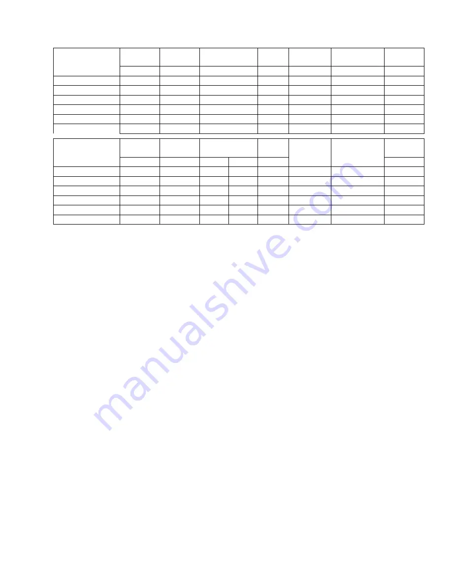
ELECTRICAL AND PERFORMANCE DATA
Models
Input
High/Low
Output
High/Low
Nominal Airflow*
Cabinet
Width
Total Unit
AFUE
Air Temp.
Rise
MBH
MBH
CFM
In.
Amps
%
°F
PV9A12N040UP11
40/26
38/24
1200
14-1/2
9
94.0
35 - 65
PV9B12N060UP11
60/39
56/36
1200
17-1/2
9
93.2
40 - 70
PV9B12N080UP11
80/52
75/49
1200
17-1/2
9
92.5
45 - 75
PV9C16N080UP11
80/52
75/49
1600
21
12
92.8
45 - 75
PV9C20N100UP11
100/65
93/60
2000
21
14
92.8
45 - 75
PV9D20N120UP11
120/78
112/73
2000
24-1/2
14
93.2
40 - 70
Models
Input
High/Low
Max. Outlet
Air Temp.
Blower
Blower
Size
Max.
Over-current
Protect
Min. Wire Size
(awg) @ 75 ft.
One Way
Operating
Wgt.
MBH
°F
HP
Amps
In.
Lbs.
PV9A12N040UP11
40/26
165
1/2
7.7
11 x 8
20
14
121
PV9B12N060UP11
60/39
170
1/2
7.7
11 x 8
20
14
135
PV9B12N080UP11
80/52
175
1/2
7.7
11 x 8
20
14
142
PV9C16N080UP11
80/52
175
3/4
9.6
11 x 10
20
14
157
PV9C20N100UP11
100/65
175
1
12.8
11 x 11
20
12
164
PV9D20N120UP11
120/78
170
1
12.8
11 x 11
20
12
180


