035-19650-001 Rev. C (0404)
Unitary Products Group
13
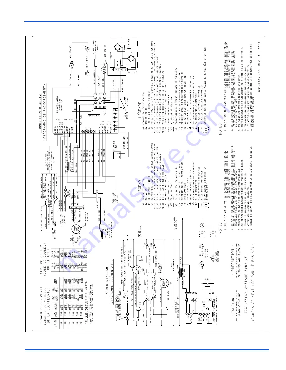
SECTION IV: WIRING DIAGRAM
FIGURE 9:
Wiring Diagram
Страница 1: ...r explosion A qualified service agency should be contacted to inspect the furnace and replace all gas controls control system parts electrical parts that have been wet or the furnace if deemed necessa...
Страница 2: ...making sure the physical support is sound without sagging cracks or gaps Examine the furnace base making sure it is physically sound without cracks gaps or sagging and has a good seal 5 Examine the fu...
Страница 3: ...Wait five 5 minutes to clear out any gas If you then smell gas STOP Follow B in the safety information above If you don t smell gas go to next step 7 Move gas control switch to the ON position Do not...
Страница 4: ...ilter size from Table 1 Removing Filters Internally Mounted Air Filters Most upflow furnaces have their filters located on the side or bottom of the furnace in a filter wire retainer located inside th...
Страница 5: ...iliary Limit and Roll out Switches for closed contacts The Control checks that the Low Fire Pressure Switch 1LP is open The Inducer Motor is energized on high speed closing the con tacts of 1LP The Co...
Страница 6: ...the furnace model being serviced Follow the procedure below to replace the motor Removal of the Variable Speed Blower Motor Assembly The procedure for removing the variable speed blower assembly 1 Dis...
Страница 7: ...l power and gas supply to the furnace 13 Check furnace operation Cleaning the Secondary Heat Exchanger 1 Follow steps 1 8 under cleaning the Heat Exchanger 2 Remove the vent piping from the vent blowe...
Страница 8: ...Dirty Filter Improperly sized duct system Incorrect blower speed selection Incorrect firing rate Faulty blower motor Faulty Control 6 Flash Reason 1LP has opened five times during one call for heat Ef...
Страница 9: ...W INDUCER LOW STAGE PRESSURE SWITCH HSI 1ST STAGE MAIN VALVE FLAME SENSE LOW CIRCULATOR HEAT SPEED 1ST STAGE LOW PRESSURE SWITCH CLOSE RECOGNITION HSI WARM UP 17 SEC IGNITION ACTIVATION PERIOD 4 SEC T...
Страница 10: ...E CIR HUM EAC XFMR LINE PARK PARK HEAT COOL 1 4 2 6 10 12 14 7 8 9 13 3 5 15 17 16 11 C G R W Y HUM EAC XFMR LINE CIR HUM EAC XFMR LINE PARK PARK HEAT COOL 19 24 25 31 26 32 33 34 50 21 22 23 27 45 28...
Страница 11: ...CHANNEL TOE PLATE 32 COVER HEAT EXCHANGER 33 PANEL FRONT Blower 34 PANEL FRONT Burner PANEL FRONT Burner 35 PANEL TOP 36 SUPPORT BURNER 37 WRAPPER CABINET Insulated WRAPPER CABINET Insulated 38 PANEL...
Страница 12: ...NAL BOTTOM FILTER RACK 17 1 2 CABINETS 21 CABINETS 24 1 2 CABINETS CONDENSATE NEUTRALIZER KIT ALL MODELS REPLACEMENT PART CONTACT INFORMATION This is a generic parts list To request a complete parts l...
Страница 13: ...035 19650 001 Rev C 0404 Unitary Products Group 13 SECTION IV WIRING DIAGRAM FIGURE 9 Wiring Diagram...
Страница 14: ...035 19650 001 Rev C 0404 14 Unitary Products Group NOTES...
Страница 15: ...035 19650 001 Rev C 0404 Unitary Products Group 15...
Страница 16: ...plies only to products installed in the United States and Canada EXCLUSIONS This warranty does not cover any 1 Shipping labor or material charges 2 Damages resulting from transportation installation o...