147
YORK INTERNATIONAL
FORM 201.18-NM3
control power is applied to the panel, if no fault condi-
tions are present. When a fault occurs which locks out
a system the respective contacts open. If chiller power
is lost or a unit fault occurs, such as a Low Water Temp
fault, contacts for all systems will open.
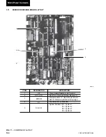
Contacts for SYS 1 are located on the bottom right of
the microprocessor panel, terminals 23 and 24. SYS 2
contacts are located on terminals 27 and 28, SYS 3 on
terminals 37 and 38, and SYS 4 on terminals 41 and
42. See Fig. 11, Page 39 for the location of these termi-
nals.
A 28VDC or 120VAC (60Hz models) or up to 240VAC
(50Hz models) external alarm circuit (supplied by oth-
ers) may be connected to these contacts. The contacts
are rated at 125VA.
If any inductive load devices (relay or
contactor) supplied by the user are in
the electrical circuit connected to the
dry alarm contacts, the device must be
suppressed at the load with a RC sup-
pressor YORK Part Number 031-
00808-000 across the inductive coil.
(Typically, several are supplied loose
with the panel). Failure to install sup-
pressors will result in nuisance faults
and possible damage to the chiller.
If the alarm circuit is applied in an ap-
plication used for critical duty (such
as process duty or cooling other criti-
cal equipment) and the alarm circuit
should fail to function, YORK will not
be liable for damages.
1.20
RUN STATUS (CHILLER)
Chiller Run Status contacts between Terminal 28 and
29 close whenever one of the systems is running. These
contacts are located on the bottom right of the Micro-
processor Board and are rated (voltage and current) the
same as the alarm contacts (Section 1.19). Also use a
suppressor, same as alarm contacts (Section 1.19). In-
dividual system “Run Status” is not available.
1.21
LEAD / LAG COMPRESSOR SELECTION
The chiller may be set up for AUTO or MANUAL Lead /
Lag. This is accomplished by programming the option
under the Program Key. Details for programming the
Manual/Auto Lead/Lag Selection are discussed in Pro-
gram Key Section 8, page 179.
When AUTO Lead/Lag is utilized, the micro attempts
to balance run time between the two compressors. A
number of conditions can occur which will prevent this
from happening. Factors determining lead/lag selection
and the resulting lead/lag determination are:
1. The micro automatically defaults the lead to SYS 1
and the lag to SYS 2 if both compressors are ready
to start (Anti-recycle Timers timed out) and com-
pressors have equal run time.
2. In YCAS 3 System models, SYS 2 is assigned first
lag and SYS 3 the second lag. The same lead/lag
assignment occurs with YCAS 4 System models
with SYS 4 assigned as the third lag. Individual
system run status is not present.
3. If all compressors are ready to start (Anti-recycle
timers timed out), the compressor with the lowest
run hours will start first.
4. If all compressors are waiting to start (Anti-recycle
timers have not timed out), the micro will assign
the lead to the compressor with the shortest anti-
recycle time in a an effort to provide cooling
quickly.
5. If the lead compressor is locked out, faulted and
waiting to restart, SYS switch on the microboard is
off, or a run permissive is keeping an individual
system from running, the lag (first lag in YCAS 3
System and YCAS 4 System models) compressor
is swapped to the lead. This is true regardless of
whether the lag compressor is ON or OFF.
MANUAL Lead/Lag selection will be automatically
overridden by the micro to allow the lag compressor to
automatically become the lead anytime the selected lead
compressor shuts down due to a lock-out, lead system
faults and is waiting to restart, lead switch on the micro
board is in the OFF position, or if a run permissive is
keeping the lead of the system off. Automatic
switchover in MANUAL mode is provided to try to
maintain chilled liquid temperature as close to setpoint
as possible.
1.22
3 OR 4 COMPRESSOR
CHILLER CONFIGURATION
The EPROMs are identical in 3 and 4 compressor units.
To place the software in 3 compressor mode, a jumper
must be connected between J4-3 and +24V on the
microboard. This connection can be made between
terinals 13 and 75 on the terminal block. If the jumper is
not installed, the unit will operate as a 4 compressor unit.
8
Содержание MILLENNIUM YCAS 250
Страница 36: ...36 YORK INTERNATIONAL FIG 8 POWER PANEL SECTION CONT D OPTIONS PANEL LAYOUT TYPICAL 00246VIP Installation...
Страница 61: ...61 YORK INTERNATIONAL FORM 201 18 NM3 This page intentionally left blank 7...
Страница 65: ...65 YORK INTERNATIONAL FORM 201 18 NM3 LD04179 7...
Страница 79: ...79 YORK INTERNATIONAL FORM 201 18 NM3 This page intentionally left blank 7...
Страница 83: ...83 YORK INTERNATIONAL FORM 201 18 NM3 This page intentionally left blank 7...
Страница 87: ...87 YORK INTERNATIONAL FORM 201 18 NM3 LD04268 7...
Страница 127: ...127 YORK INTERNATIONAL FORM 201 18 NM3 COMPRESSOR COMPONENTS CONT D FIG 65 COMPRESSOR COMPONENTS LD03669 7...
Страница 128: ...128 YORK INTERNATIONAL COMPRESSOR COMPONENTS CONT D FIG 66 COMPRESSOR COMPONENTS LD03670 Technical Data...
Страница 129: ...129 YORK INTERNATIONAL FORM 201 18 NM3 COMPRESSOR COMPONENTS CONT D FIG 67 COMPRESSOR COMPONENTS LD03671 7...
Страница 195: ...195 YORK INTERNATIONAL FORM 201 18 NM3 This page intentionally left blank...

