

Notes:
•
Air handler units have been tested to UL 60335-2-40 / CSA 22.2 No. 236 standards up to 0.6 in. W.C. external static pressure.
•
Dry coil conditions only, tested without filters.
•
For optimal performance, external static pressures of 0.2 in. W.C to 0.5 in. W.C are recommended. Heating applications tested at 0.5 in. W.C. external static pressure.
Above 0.5 in. W.C., CFM is reduced by 2% per 0.1 in. increase in static.
•
Low speed cooling used only with two stage outdoor units. Speed is preset to 65% of high speed.
•
Dehumidification speed is 85% of jumper selected cool tap.
•
Any compressor operation uses HI COOL and LO COOL DIP switches. Indoor heating operates off the heatkit selection and the HEAT DIP switches.
•
At some settings, low cool and/or low heat airflow may be lower than what is required to operate an airflow switch on certain models of electronic air cleaners. Consult
the instructions for the electronic air cleaner for further details.
•
Airflow (CFM) indicator light (LED2) flashes once for every 100 CFM (for example, 12 flashes is 1200 CFM) - blinks are approximate ±10% of actual CFM.
Airflow selection
When not using communicating functionality, you must set the airflow
and comfort setting selection switches correctly at the time of installation
for correct system operation. Place switches in the correct locations
based on the information shown in
. An example of switch posi-
tions is shown below in
. 0 indicates the OFF position and 1 indi-
cates the ON position. The airflow configuration switches are located in
the SW4 switch bank.
Inputs to the air handler control board pass to the motor, which deter-
mines the target CFM to deliver. Refer to the
Installation Manual
for more
information on these inputs.
These variable speed air handlers are designed to deliver constant
airflow (CFM) regardless of the external static pressure (ESP) in the
ductwork. Therefore, if too many supply registers are closed, a filter
becomes clogged, or there is a restriction in the ductwork, the motor
automatically operates at a higher speed to compensate for the higher
ESP. This may result in a higher operating sound level and motor
damage.
Table 2:
Airflow data (CFM)
DIP Switch
B18B
B24C
B36D
C36D
C42F
D42F
High cool Low cool High cool Low cool High cool Low cool High cool Low cool High cool Low cool High cool Low cool
000
575
400
700
475
800
550
825
600
1100
700
1125
675
001
625
450
725
525
900
600
900
650
1200
750
1225
875
010
675
475
800
575
975
650
1000
700
1300
800
1325
925
011
725
525
850
625
1075
700
1050
750
1400
850
1425
1000
100
775
550
925
650
1150
775
1150
825
1500
925
1550
1075
101
850
575
975
700
1250
825
1225
850
1625
975
1675
1150
110
900
625
1075
725
1325
900
1300
900
1725
1050
1775
1225
111
950
650
1100
775
1400
950
1350
950
1825
1100
1875
1275
DIP Switch
C48G
D48G
C60H
D60H
D60J
High cool Low cool High cool Low cool High cool Low cool High cool Low cool High cool Low cool
000
1150
725
1125
700
1400
975
1400
975
1375
925
001
1250
775
1225
875
1525
1075
1550
1075
1475
1050
010
1350
850
1325
925
1650
1150
1700
1150
1750
1125
011
1450
900
1425
1000
1800
1250
1850
1250
1875
1225
100
1575
975
1550
1075
1925
1350
2000
1350
2000
1350
101
1675
1025
1675
1150
2050
1425
2125
1425
2000
1400
110
1775
1100
1800
1225
2050
1525
2125
1550
2000
1475
111
1875
1150
1900
1275
2050
1600
2125
1650
2000
1575
Figure 2:
DIP-10
ON
DIP Switch example: 0101000110
1
2
3
4
5
6
7
8
9
10
A1708-001
NOTICE
Incorrect airflow and comfort settings may result in decreased system
efficiency and performance.
Clearances
It is essential to provide the following clearances:
•
Refrigerant piping and connections - minimum 12 in.
•
Maintenance and servicing access - minimum 36 in. from the front
of the unit for blower motor or coil replacement
•
Condensate drain lines routed to clear filter and panel access
•
Filter removal - minimum 36 in.
•
The supply air ductwork connected to this unit is designed for 1 in.
clearance for the first 18 in. of combustible materials if an electric
heat kit accessory is installed.
•
A combustible floor base accessory is available for downflow appli-
cations of this unit, if required by local code.
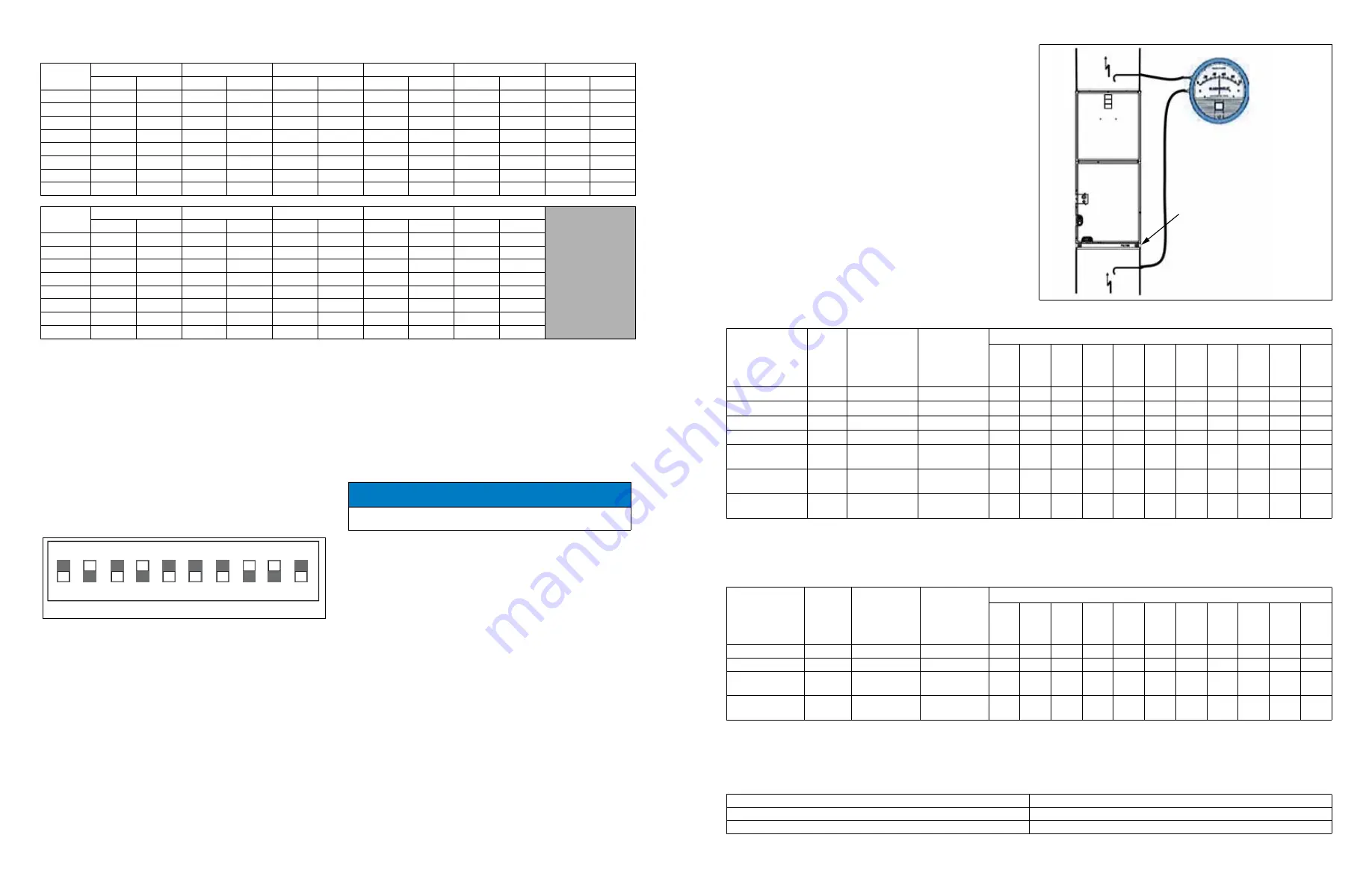
External duct static
Measure the supply air static pressure. Record this positive number.
Measure the return air static pressure. Record this negative number.
Treat the negative number as a positive and add the two numbers
together to determine the total external system static pressure. If a filter
rack is installed on the return air end of the air handler or indoor coil
section, make sure to measure the return air duct static between the filter
and the indoor coil.
Figure 3:
Duct static measurements
Take measurements here if using
a filter rack.
Return air static must be taken
between the filter and indoor coil.
A1704-001
Table 3:
Electrical heat: minimum fan CFM for single-phase heatkits
Heater kit
models
1,2
Nominal
kW
at 240 V
Airflow
configuration
heat dip switch
setting*
Aux heat
configuration
heatkit
selection dip
switch setting
Air handler models (CFM
3
)
B18B B24C B36D C36D
C42F
D42F
C48G D48G C60H D60H
D60J
8HK(0,1)6500206
2.4
00
0001
625
650
625
825
825
825
825
825
825
825
825
8HK(0,1)6500506
4.8
00
0010
650
650
650
825
825
825
825
825
825
825
825
8HK(0,1)6500806
7.7
00
0011
750
800
750
1100
1100
1150
1100
1150
1100
1150
1150
8HK(0,1)6501006
9.6
00
0100
790
950
750
1100
1100
1500
1100
1500
1100
1500
1500
8HK(1,2)6501506
14.4
00
0101
—
650,
950
650,
975
825,
1100
825,
1100
825,
1575
825,
1100
825,
1575
825,
1100
825,
1575
825,
1700
8HK(1,2)6502006
19.2
00
0110
—
—
750,
975
1100,
1300
1100,
1300
1325,
1575
1100,
1300
1325,
1575
1100,
1300
1325,
1575
1500,
1700
8HK(1,2)6502506
24
00
0111
—
—
—
—
—
—
—
1325,
1650
—
1325,
1650
1500,
1800
1. (0,1) - 0 = no service disconnect or 1 = with service disconnect.
2. (1,2) - 1 = with service disconnect, no breaker jumper bar or 2 = with service disconnect and breaker jumper bar.
3. For minimum fan CFM, if there are two values present, the first value is low-stage CFM (W1) and the second value is full-stage CFM (W1+W2). If higher kW/CFM is
needed for low-stage, see
* To increase airflow by approximately 20%, adjust the HEAT DIP switches from 00 to 01.
Table 4:
Electrical heat: minimum fan CFM for three-phase heatkits
Heater kit
models
1,2
Nominal
kW
at 240 V
Airflow
configuration
heat dip switch
setting*
Aux heat
configuration
heatkit
selection dip
switch setting
Air handler models (CFM
3
)
B18B B24C B36D C36D
C42F
D42F
C48G D48G C60H D60H
D60J
8HK06501025
9.6
00
1000
790
950
1150
1150
1150
1500
1150
1500
1150
1500
1700
8HK06501525
14.4
00
1001
—
950
1150
1150
1150
1575
1150
1575
1150
1575
1700
8HK16502025
19.2
00
1010
—
—
1150,
1150
1150,
1300
1150,
1400
1500,
1575
1150,
1300
1500,
1575
1150,
1300
1500,
1575
1700
8HK16502525
24
00
1011
—
—
—
—
—
—
—
1575,
1650
—
1575,
1650
1700,
1800
1. (0,1) - 0 = no service disconnect or 1 = with service disconnect.
2. (1,2) - 1 = with service disconnect, no breaker jumper bar or 2 = with service disconnect and breaker jumper bar.
3. For minimum fan CFM, if there are two values present, the first value is low-stage CFM (W1) and the second value is full-stage CFM (W1+W2). If higher kW/CFM is
needed for low-stage, see
* To increase airflow by approximately 20%, adjust the HEAT DIP switches from 00 to 01.
Table 5:
Aux heat configuration - stage 1 kW dip switch settings
W1 = W1
00, 01
W1 = W2
10
W1 = W1 + W2
11