background image

38 

P5417054

●  The total number of connected indoor units is indicated on the LCD (Liquid Crystal Display).  In 

the case of a twin combination (set of two indoor units), the total number of the connected indoor 

units is displayed as 

“2 units”

, and where there is a triple combination (set of three indoor units), 

the total number of the connected indoor units is displayed as 

“3 units”

.

●  If the number indicated is not equal to the actual number of connected indoor units, the auto-

address function is not performing correctly due to incorrect wiring or electrical interference. Turn 

OFF the power supply, and resolve the wiring issue after verifying the following items; (Do not 

repeat turning ON and OFF within a 10 second timespan.)


The power supply to the indoor unit is not turned ON or there is an incorrect wiring issue.


Incorrect connection of the interconnecting cable between indoor units or a poorly connected 

controller cable.


Incorrect setting of the rotary switch and DIP switch for the indoor unit printed circuit board 

(PCB). (The setting is overlapped.)

●  Press “

 On/Off” to start the Test Run.

●  Press “

” and set each item.

b.  Press “  On/Off”. 

The RUN indicator turns ON and the operation starts.  At this time, a two-hour OFF timer will be set 

automatically.  

c.  Press “ ” or “ ”, select “LOUV.” and select “   ” (auto-swing) by pressing “ ” or “ ”.  The auto 

swing operation will start.  Check the operating sound at the louvers.  If abnormal sound is not 

generated, press “ ” or “ ” again to stop the auto swing operation.  If abnormal sound is generated 

from the louvers, remove the face panel and adjust the louver accordingly.

“A”

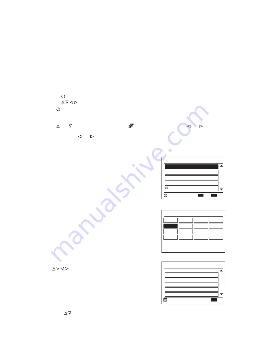
d.  Verify that the motion sensor is operating 

correctly as in the following steps: (in cases of 

the decorative panel with the motion sensor).
1.  Press and hold “Menu” and “Back/Help” 

simultaneously for at least three seconds 

during the Test Run mode. 

The check menu screen “A” is displayed.

Check Menu

Function 5

Model Display

Alarm History Display

Check 2

01

/

02

Check 1

Sel.

Entr

Rtrn

OK

Back

2.  Select 

“Check 1”

 at the check menu and 

press 

“OK”

. (Screen “B” will be displayed.)

  (This screen is NOT displayed when only 

one indoor unit is connected to the wired 

controller. In this case, screen “C” will be 

displayed.)

3.  Select the indoor unit by pressing 

” and press “OK”. 

The check data screen “C” will be displayed.

“B”

“C”

Model Display:01-02 

Model:F .08

01-01

01-02

01-03
01-04

IDU  : ****** 

S/N:000000

ODU  : ****** 

S/N:000000

Check 1:01-03

01

/

07

Next Page

Rtrn

q1 

50

P2 

10

P1 

00

L4 

00

Item 

Value

L3 

00

Back

4.  Press “

” to change the screen until it displays the check screen “q2” ~ "q6".

Содержание HIC4008B21S

Страница 1: ...TIONERS Type Model 4 Way Cassette H Y C IC4008B21S H Y C IC4012B21S H Y C IC4015B21S H Y C IC4018B21S H Y C IC4024B21S H Y C IC4030B21S H Y C IC4036B21S H Y C IC4048B21S IMPORTANT READ AND UNDERSTAND...

Страница 2: ...to verify that your product model numbers have the same version of software Access the main printed circuit board in each product Locate a white sticker with a P XXXX number or Connect a service check...

Страница 3: ...been designed for a specific temperature range For optimum performance and long life operate this unit within the range limits according to the table below This manual should be considered as a perma...

Страница 4: ...General Check 21 8 2 Electrical Wiring Capacity 21 8 2 1 Field Minimum Wire Sizes for Power Supply 21 8 2 2 Details of Electrical Wiring Connection 22 8 3 Position of Electrical Wiring Connection 23...

Страница 5: ...d are attached to the unit Refer back to these safety instructions as needed This system should be installed by personnel certified by Johnson Controls Inc Personnel must be qualified according to loc...

Страница 6: ...a hospital or other facility where electromagnetic waves are generated from nearby medical and or electronic devices be prepared for noise and electronic interference Electromagnetic Interference EMI...

Страница 7: ...tc Where the blower devices such as ceiling fan ventilating fan etc affect the air flow from the indoor unit Where weather affects directly the surface of the sensor Where the lens surface may smudge...

Страница 8: ...mpressor activates with the stop valve opened the refrigerant cycle will become subjected to extremely high pressure which can cause an explosion or fire Tighten the flare nut with a torque wrench in...

Страница 9: ...door or outdoor units without turning OFF the main power supply After stopping operation be sure to wait at least five minutes before turning off the main power switch Otherwise water leakage or elect...

Страница 10: ...ceiling surfaces Any variance or inclination can cause moisture to back up into the condensate pan overflow and seepage onto ceiling or wall surfaces and cause damage to carpeted surfaces or furniture...

Страница 11: ...essive force is applied as a result of mishandling of the unit during installation 3 Before Installation 3 3 Factory Supplied Accessories 1 Check to ensure that the following accessories are packed wi...

Страница 12: ...objects inside the indoor unit and verify that no foreign objects remain inside in the indoor unit before the installation and Test Run Failure to do this can result in equipment failure and damage t...

Страница 13: ...d condensation 8 If installing the indoor unit to a high ceiling the warmed air will remain near the ceiling during heating operation Thus a parallel installation of a circulator is recommended 9 Do n...

Страница 14: ...16 Dimension of Opening 33 1 16 Unit Size 29 15 16 Dimension of Suspension Bolts Piping Connection Side Condensate Piping Connection Side Unit inch 4 Positions of Suspension Bolts M10 or W3 8 4 1 2 x...

Страница 15: ...allation comes with a scale printed on a portion of the outer packaging Detach this area with the printed scale to use in sizing and checking the opening Refer to the procedure shown in Item 6 2 Mount...

Страница 16: ...oor Unit Nut Field Supplied Surface of Ceiling Approx 1 15 16 inches Washer Accessory Washer with Insulation Accessory 4 Mounting Nuts and Washers Mount nuts and washers onto the suspension bolts befo...

Страница 17: ...h 5 0 mm The pattern board template for the installation and the checking scale are printed on the packing Cut off the checking scale for dimension of opening from packing to adjust the position of th...

Страница 18: ...e scale of the pattern board template while maintaining the vertical alignment of the indoor unit 2 See that the secured screws for the panel are tightened Tighten the securing screws for the panel un...

Страница 19: ...the cutting operation After the cut is made blow out each pipe with dry compressed air or nitrogen to remove this residue before making pipe connections 6 1 Piping Materials 1 Tolerances of refrigeran...

Страница 20: ...or the outdoor unit 10 If temperature and humidity inside the ceiling exceed 80 6 F 27 C RH80 condensation occurs on the surface of the accessory insulation Wrap additional insulation approximately 3...

Страница 21: ...ose Accessory Twisted Incompletely Insertion Check to ensure that the condensate pipe discharges moisture properly If connected incorrectly it can cause structural damage to indoor wall and ceiling su...

Страница 22: ...nd spillover into the room after unit operation has stopped Hose Clamp Accessory Tightening Torque 2 2 2 6 ft lbs Condensate Pipe Connection Condensate Hose Accessory Max 11 13 16 inches 1 1 8 inches...

Страница 23: ...d at the pipe end and that no moisture leakage occurs If the end of the condensate pipe cannot be checked visually pour another 50 to 67oz 1 5 to 2 liters of water to the condensate pan If the water o...

Страница 24: ...he condensate pan The heat exchanger is heated since a slight amount of refrigerant circulates inside the indoor unit during periods of stoppage As a result moisture in the condensate pan evaporates c...

Страница 25: ...that the indoor fan and the outdoor fan have stopped before attempting any electrical wiring work or for any scheduled electrical work that is being performed Tighten screws according to the followin...

Страница 26: ...lect the wiring size GFCI in accordance with the regulations for each region the Installation and Maintenance Manual and the dedicated electrical circuit that must be used Outside of the indoor unit i...

Страница 27: ...unication line Terminals A B 1 and 2 of TB2 If connected the printed circuit board PCB will be destroyed 7 Tightly clamp the power supply wiring and communication cables using the cable band inside th...

Страница 28: ...ll be seriously damaged and will not recover L1 R L2 AC 208V 230V Incorrect Wiring Reconnect wirings correctly 5V A B 1 2 S L1 R L2 AC 208V 230V 5V A B 1 2 S ON OFF DSW7 Set No 1 Pin at ON side PCB 1...

Страница 29: ...e wired controller Remote ON OFF function settings No 1 2 and 3 External Input Output Function Power supply ON OFF functions No 1 and 2 Function Selection Prohibiting the wired controller after manual...

Страница 30: ...vailable with two wired controllers 3 The individual louver function is not designed for blocking the air outlet If the air outlets are required to be blocked a three way outlet parts set shall be use...

Страница 31: ...I U with Motion Sensor The communication cable for the wired controller I U with Motion Sensor I U with Motion Sensor I U with Motion Sensor Wired Controller Wired Controller Main Setting is Available...

Страница 32: ...S G F C I G F C I R L1 S L2 Mp N R L1 S L2 Mp N R L1 S L2 Mp N R L1 S L2 Mp N R L1 S L2 Mp N R L1 S L2 Mp N Where ambient temperature changes drastically Where excessive force or vibration is applied...

Страница 33: ...appropriately and firmly fastened to guarantee against electrical short sparks and flame Piping Cover Cable Band Wiring Support Plate Electrical Box Cover Wiring Opening Electrical Box PCB Screw for E...

Страница 34: ...F 1 2 3 4 5 6 ON OFF 1 2 3 4 5 6 ON OFF 1 2 3 4 5 6 ON OFF 5 Unit Model Code Setting DSW4 No setting is required It is for setting the model code of the indoor unit 8 6 DIP Switch Settings 1 Turn OFF...

Страница 35: ...P Switch adjustments otherwise the settings will not take effect NOTES The solid square symbol signifies the ON and OFF positions for DIP switches The diagrams show original settings before shipment W...

Страница 36: ...e indoor units are running Thermo OFF The outdoor unit and some indoor units stay on but don t run 8 9 Individual Louver Settings Number of Louver Outlets This setting is available only for the indoor...

Страница 37: ...OK is pressed the screen will return to Item 5 Regarding the Individual Louver Setting the louver selected at Item 5 will be set as Number 1 and the other louver numbers will be changed automatically...

Страница 38: ...he controller is 1 one In this case 4 is displayed Press All to select all the indoor units connected to the wired controller OK Test Run Menu Input Output Thermistor Selection Function Selection 01 0...

Страница 39: ...2 Not Available Available Control of Dew Condensation Prevention K8 Not Available Available Automatic COOL HEAT Operation b8 Not Available Available Dual Setpoint R1 Not Available Available A Cooling...

Страница 40: ...tback function can be selected on the wired controller Refer to Section 8 11 Function Selection by Wired Controller of the manual for details OK Test Run Menu Input Output Thermistor Selection Functio...

Страница 41: ...ions 3 Check to ensure that the main power supply has been turned ON for more than 12 hours to warm up the compressor oil by the crankcase heater 4 Verify that all DIP Switch settings are correct Refe...

Страница 42: ...ON and the operation starts At this time a two hour OFF timer will be set automatically c Press or select LOUV and select auto swing by pressing or The auto swing operation will start Check the opera...

Страница 43: ...q6 is neither 0 nor 100 If the value displayed is 0 or 100 repeat the procedure from Item 1 If the same value reappears it may be a malfunction of the motion sensor NOTE Refer to the operator s manual...

Страница 44: ...ed controller a loose or severed connection In this case verify Section 9 3 Alarm Code and perform the appropriate troubleshooting measures Consult with an authorized service engineer if the problem c...

Страница 45: ...insufficient total indoor unit capacity code 32 Incorrect setting of other indoor unit number Problem with a different Indoor Unit in the same refrigerant cycle Failure at the power supply defective P...

Страница 46: ...2017 Johnson Controls Inc Code No LIT 12012613 Issued November 2017 P5417054...

Отзывы: