background image

YORK INTERNATIONAL

6

INTRODUCTION

GENERAL

This manual has been prepared as a guide for installing,
operating and maintaining CurbPak Air Handling Units.
YORK has produced a quality product that is adapt-
able to almost any comfort or industrial application.
However, proper installation, operation and maintenance
must be followed to realize the full capacity and life of
the units.

This instruction contains general recommendations, but
specific requirements may apply to the individual instal-
lation. Such requirements are outlined in federal, state
and local safety codes. Strict compliance with these
codes, and strict adherence to these instructions are
the responsibility of the user. Particular attention should
be given to electrical wiring and other safety elements
such as design working pressures and requirements of
the Government Clean Air Act Amendments as it ap-
plies to refrigerant types and charges. General safety
practices are covered in AMCA Publication 410-90.

Read the entire instruction before installing or operat-
ing the air handler. Specific details and requirements
apply that require careful consideration to avoid dam-
age to the equipment and injury to the installer or op-
erator.

The installer should pay particular attention to the fol-
lowing symbols:

Notes are intended to clarify or make
the installation easier.

Cautions are given to prevent equip-
ment damage.

Warnings are given to alert the in-
staller that personal injury and/or
equipment damage may result if in-
stallation, operation and mainte-
nance procedures are not handled
properly.

DESCRIPTION

The YORK CurbPak is specifically custom designed
for outdoor rooftop application or other specified loca-
tions. This unit is of weatherproof design with a roof
that slopes 1/4 inch per foot minimum. The roof over-
hangs the side panels by three (3) inches to prevent
water infiltrating the unit. All side panels overhang roof
curbs to prevent water leakage. A “U” constructed base

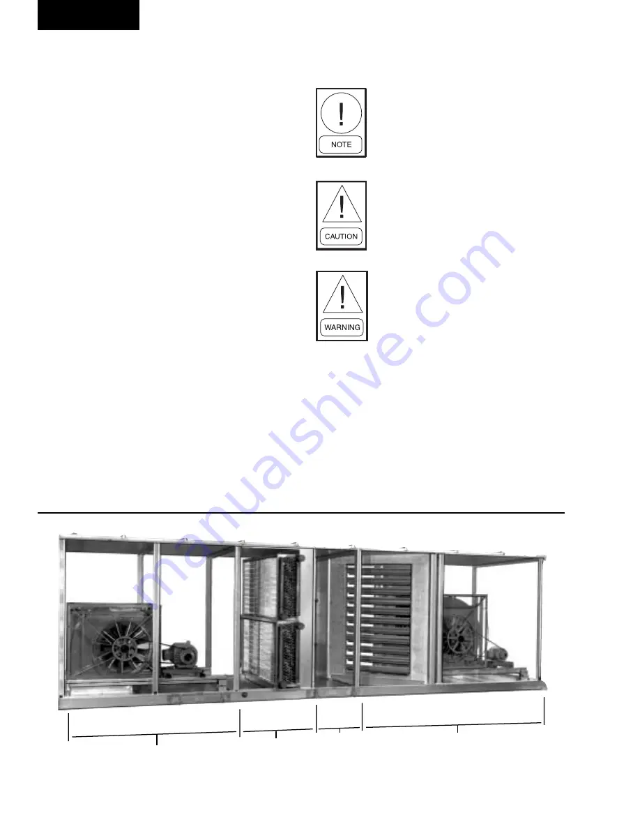
FIG. 1 – 

CUTAWAY OF CURBPAK SHOWING VARIOUS SEGMENTS

SUPPLY FAN SEGMENT

COIL

SEGMENT

FILTER

SEGMENT

INLET/ECONOMIZER

SEGMENT WITH

DWDI RETURN AIR FAN

25514A

Introduction

Содержание CURBPAK CP23

Страница 1: ...INSTALLATION OPERATION MAINTENANCE CURBPAK AIR HANDLING UNITS New Release Form 100 10 NOM2 301 MODELS CP65 THROUGH CP1030 ROOF MOUNTED SINGLE ZONE 00466vip...

Страница 2: ...s indi vidual shall also be familiar with and comply with all applicable governmental standards and regulations per taining to the task in question SAFETY SYMBOLS The following symbols are used in thi...

Страница 3: ...lications 32 Factory Packaged Controls and Motor Control Center 33 3 Operation Startup Checklist 34 Pre operational Check 34 Temperature Limitations 35 Static Pressure Limits 35 Safety Check Warning 3...

Страница 4: ...que Requirements to Operate Variable Inlet Van VIV 26 31 Typical Motor Data Nameplate 27 32 Motor Control Centrifugal Diagram 28 Figure Page 33 Wiring Diagram Starter Panel 29 34 Wiring Diagram 2 Spee...

Страница 5: ...r Data FP V Economizer 40 8 Fan Bearing Lubrication Intervals 42 9 1 Motor Bearing Lubrication Intervals 42 9 2 Motor Bearing Service Conditions 42 9 3 Motor Bearing Lubrication Interval Multiplier 43...

Страница 6: ...lication 410 90 Read the entire instruction before installing or operat ing the air handler Specific details and requirements apply that require careful consideration to avoid dam age to the equipment...

Страница 7: ...plied to direct the air flow to bypass the specified coil for fresh air operation or through another coil to satisfy applica tion versatility This segment is used for coil capacity control when coil c...

Страница 8: ...rict Office attn Sales Person Failure to perform the long term storage requirements will void the warranty SAFETY PRACTICES Air Handling Units are designed to provide safe and reliable service when op...

Страница 9: ...Filter 2 RF Rigid Filter 12 BF Bag Filter 21 32 CF Carbon Filter HF HEPA Filter TABLE 1 SEGMENT IDENTIFICATION SEE FIG 2 Inlet Segments MB Inlet w Dampers 0 30 or 100 OA 0 or 100 RA EE Economizer 100...

Страница 10: ...YORK INTERNATIONAL 10 SEGMENT AVAILABILITY Introduction LD06684 FIG 2 SEE TABLE 1...

Страница 11: ...width of the unit must be provided on one side of the unit for removing the coil ROOF PITCH LIMITATIONS 1 2 Inch Foot Although level installations are preferred YORK units can be installed in any dire...

Страница 12: ...nstallation Site Area of roof on which curb is to be installed must be level see Roof Pitch limita tions and structurally adequate to support the com bined weight of curb and unit Be sure the supporti...

Страница 13: ...evel 4 Curb material is 14 gauge galvanized steel unpainted for 14 18 22 12 gauge for 26 30 curbs 5 Curbs must be fully supported by the roof structure A TOTAL UNIT LENGTH FROM YORKWORKS 9 B TOTAL SEG...

Страница 14: ...nit weights in this instruction Unit weights are listed with each unit submittal drawing These draw ings must be referred to when selecting a crane for rigging and figuring roof weight loads Contact y...

Страница 15: ...asher and a nut Place bolts and hardware into every hole 7 Replace screws in wall panel that were removed in Step 3 8 Apply caulking and place roof seam cap onto raised seam Then bend the end piece do...

Страница 16: ...ter than 7 for diverging elements DUCT CONNECTION GUIDELINES See Figures 14 and 15 All intake and discharge air duct connections to the unit may be made directly to the unit with the exception of exte...

Страница 17: ...SOUND AND VIBRATION TRANSMISSION All roof mounted air handling units generate some sound and vibration that may or may not require some special treatment of the air conditioned space The noise gen er...

Страница 18: ...ions See Figure 17 6 Horizontalductsshouldbepitchedandprovidedwith drainage outlets as illustrated by the system de signer 7 Ducts should be installed at a height sufficient to install roofing and fla...

Страница 19: ...BOLTS FOR ATTACHING PIPE CHASE BRKT BUTYL TAPE LAYER OF BUTYL TAPE Support all connecting piping independently of the coils Provide swing joints or flexible fittings in all piping con nections particu...

Страница 20: ...pe to face side of the header cover to cover the holes around the perimeter Tape provided in package 4 Lift pipe chase onto frame 100 lbs and align holes to restart cap screw that were removed from co...

Страница 21: ...orientation of the re frigerant distributor is not critical but the distributor tubes must not be kinked or bent in a non uniform configura tion See Figure 21 An individual expansion device must be p...

Страница 22: ...DENSATE DRAIN PIPING The majority of cooling coils are located in the units so that the supply air is drawn through them This results in the condensate being subjected to negative static pressure Unle...

Страница 23: ...nfigu ration with a drain connection on each side Main coil drain pans and all auxil iary floor drain pans in the unit must be properly trapped and charged with water before the units are started BELT...

Страница 24: ...nkage design is not provided by YORK when factory packaged con trols are not included Air flow con trol dampers may be operated with pneumatic or electric actuator con trollers These items should be s...

Страница 25: ...rees with respect to the jack shaft crank arm to which it is attached If not maximum power against rotational motion will be compro mised See Figure 29 4 Position of Vanes When completely open vanes a...

Страница 26: ...The outdoor and the return air dampers are operated by individual ac tuators As the outdoor air dampers are opened by the damper actuator the return air dampers are closed If the economizer operation...

Страница 27: ...ail control components pre maturely All penetrations through the unit housing pipe chase or cabinets must be sealed inside and outside All exposed electrical connections must be checked for tightness...

Страница 28: ...YORK INTERNATIONAL 28 Installation LD03621 MOTOR CONTROL CONFIGURATION DIAGRAM FIG 32 MOTOR CONTROL CONFIGURATION DIAGRAM...

Страница 29: ...independent control of motors 4 Install safeties between Terminals 5 6 or 7 8 Remove Jumpers J2 and J3 accordingly 5 TB not installed if internal rotary thru the door disconnect is present 6 TB1 to b...

Страница 30: ...ry control contact rated at min 2A 115V 3 Connect remote control signal for motor stop start at Terminals 5 6 4 Install safety between Terminals 7 8 Remove Jumper J1 accordingly 5 TB not installed if...

Страница 31: ...EQUENTIALLY IN THE REVERSE ORDER i e 3 2 1 NOTES 1 FOR SUPPLY CONNECTIONS USE MIN AWG COPPER CONDUCTORS SUITABLE FOR AT LEAST 78 C 167 F 2 SUPPLY VOLTAGE PHASE CONTROL VOLTAGE 3 FIELDTERMINALS SUITABL...

Страница 32: ...fan control for vari able air volume systems The Air Modulator varies the speed of the fan to match the VAV load requirements The Air Modulator takes maximum advantage of the relation between fan spe...

Страница 33: ...ro priate options can control monitor and diagnose those points that are necessary to maintain optimum perfor mances There are three options available Factory mounted End Devices Factory mounted End D...

Страница 34: ...ls in place 2 Remove the shipping hold down bolts and shims at the spring isolators Note Do not remove func tional bolts from seismic isolators 3 Recheck the tightness of the isolator mounting hard wa...

Страница 35: ...eck is made Under no condition should the units be allowed to con tinue to operate when excessive unit vibration is appar ent Permanent damage may result which will not be covered under the warranty i...

Страница 36: ...proper tension See section Belt Adjustment An incorrectly aligned and tensioned belt can substantially shorten belt life or overload blower and motor bearings shortening their life expectancy Abelt t...

Страница 37: ...2 86 1 FC 18 X 18 N A 15 254T 2 86 215 2 FC 18 X 18 L YES 20 256T 2 86 3 AF 15 YES 15 254T 2 04 4 AF 18 YES 20 256T 2 86 1 FC 20 X 20 N A 25 284T 4 38 250 2 FC 20 X 20 L YES 30 286T 4 25 3 AF 18 YES...

Страница 38: ...X 36 N A 60 364T 13 74 2 FC 36 X 36 L YES 60 364T 12 70 1030 3 FC 40 X 40 N A 60 364T 17 27 4 AF 40 YES 100 404T 17 27 5 AF 44M YES 100 404T 20 50 6 AF 49M YES 100 404T 24 90 TABLE 4 FORWARD CURVED AI...

Страница 39: ...24 20 256T 7 0 2162 3 AF 27 25 284T 7 0 1999 1 AF 24 20 256T 7 0 2162 250 2 AF 27 25 284T 7 0 1999 3 AF 30 30 286T 7 0 1799 1 AF 24 20 256T 7 0 2162 305 2 AF 27 25 284T 7 0 1999 3 AF 30 30 286T 7 0 17...

Страница 40: ...215T 3 1708 250 1 AF 27 10 215T 3 1558 305 1 AF 30 15 254T 3 1402 350 1 AF 33 15 254T 3 1275 400 1 AF 36 15 254T 3 1071 460 1 AF 36 20 256T 3 1071 530 1 AF 40 20 256T 3 971 680 1 AF 49 30 286T 3 797...

Страница 41: ...maximum grease ca pacity for the size bearing Relubrication is generally accompanied by a temporary rise in operating temperature Excess grease will be purged at seals Fan Bearing Lubricant A Lithium...

Страница 42: ...als are for ball bearings For roller bearings divide the listed lubrication interval by 2 For 6205 and 6806 bearings For 6807 bearings consult oil mist lubrication MN410 Relubrication interval for 620...

Страница 43: ...GREASE NEMA IEC OD WIDTH GREASETO TO BE ADDED BEARING Dmm Bmm ADD IN3 TEASPOON OZ GRAMS UP TO 210 INCL 132 6307 80 21 0 30 8 4 0 6 2 0 OVER 210 TO 280 INCL 180 6311 120 29 0 61 17 1 2 3 9 OVER 280 TO...

Страница 44: ...is could result in damaging the bearing motor pulleys or motor base See drive label on fan housing adjacent to drive for specific details on tension When it is necessary to replace one belt in a given...

Страница 45: ...nuisance trip ping of the motor overloads and or mo tor failure and or shaft failure BELT REPLACEMENT Always replace belts as a set Follow the steps below to replace belts 1 Release the tension on th...

Страница 46: ...etely smooth Drive the shaft in the opposite di rection and file smooth the set screw marks Con tinue to clean the shaft of all dirt and residuals 7 To remove the key use a rubber mallet or brass bar...

Страница 47: ...nd replacing the bearings care should be taken to ensure that the area where the bearings fit on the shaft does not become scored or damaged The shaft in this area should be thoroughly cleaned before...

Страница 48: ...locking devices are used to secure bearing s to the fan shaft Refer to the instructions packed with bearings for special information Figure 47 is a typical bearing with a setscrew type locking de vic...

Страница 49: ...in the housing Alternate Torquing of Set Screws Step 1 Torque A to 1 2 recommended torque Step 2 Torque B to full minimum recommended value Step 3 Torque A to full recommended value TABLE 10 TORQUE FO...

Страница 50: ...each end of the coil In cases where two coils are stacked one on top of the other the coils can be re moved as a single unit or individually If removed as a single unit provisions should be accessibl...

Страница 51: ...l fresh air dampers go to the full closed position The water FIG 53 DETERMINING LEFT OR RIGHT HAND COIL CONNECTION DRIVE SIDE circulation pumps must keep circulating water through the coils and or aux...

Страница 52: ...except when in blow through arrangement they are either front or rear loaded HEPA will always be front loaded 3 The number in defines how many rows high with that particular filter pattern UNIT SIZE 6...

Страница 53: ...cific filter arrangements 2 Filters are side loaded 3 The number in defines how many rows high with that particular filter pattern UNITSIZE 65 85 105 125 170 215 250 305 350 400 460 530 680 860 1030 A...

Страница 54: ...144 192 240 288 336 432 504 576 672 864 960 1152 Filter 12 x 24 12 12 24 24 24 36 48 48 Size 24 X 24 12 24 24 24 48 48 72 72 108 108 144 144 192 240 288 Lbs Carbon 155 213 261 309 426 522 639 735 959...

Страница 55: ...ther high temperature applications can be served using an alumi nized steel Holding Frame constructed without a gas ket The aluminized steel frame will tolerate tempera tures up to 900 F The standard...

Страница 56: ...ervice Latch 1 Nominal or Upstream Header Filters None or L 10 DriPak Downstream VariCel VariCel V 2 Upstream L 30 BioCel 5700 AmerFrame 4 Upstream L 50 2 Nominal Upstream Filters None or L 20 AmAir D...

Страница 57: ...UCTWOR SPRING O O OW OW GASKET T CELL SIDE E CELL SIDE VISUAL CONTROL CLAMP ADJUST BOLT HEAD FLUSH WITH CLAMP BEVEL SEAL FRAME PERIMETER EXTRUSION MEDIA PACK Sealing Integrity Assured The bevel create...

Страница 58: ...bank will be 2 greater than indi cated above i e 6 x 6 bank would be 12 6 1 2 x 12 8 1 2 FIG 59A WELDED BEVEL SEAL FRAME AND CLIPS LD06610 LD06610 2 2 MAIN RUNNER PERIMETER EXTRUSION T SECTION PERIME...

Страница 59: ...to the flow of air The determination of these pressures is a very impor tant part of troubleshooting an air conditioning system The generally accepted standard instrument for mea suring these unit pr...

Страница 60: ...may replace the manometer for average air conditioning work and like the ma nometer is available in a variety of ranges The dial is only 4 inches in diameter and therefore has a limited scale several...

Страница 61: ...following formulas Vp V 4005 V 4005 Vp FIG 66 SLACK TUBE MANOMETER FIG 67 STATIC PRESSURE AIR SYSTEM 2 It is therefore a simple matter to determine the velocity fpm of an air stream so the VP can be...

Страница 62: ...l the system static pressure or the summation static pressure These pressures are of great importance when trouble shooting for causes of reduced capacity vibration and noise Changes in the cross sect...

Страница 63: ...reign material inside bearing Disassemble inspect and clean or replace bearing as required Fretting corrosion between bearing inner race and shaft Clean or replace bearing as required Ductwork too sma...

Страница 64: ...les per design specifications Unit air filters not in place Install air filters Take ammeter readings on all three phases of motor to verify accuracy of ammeter High line voltage Consult power company...

Страница 65: ...hase condition Check overload relay sizing and verify overload relays are in each of the 3 phases of the starter Motor shaft bearing damaged Replace bearing Motor overloaded Reduce load or increase vo...

Страница 66: ...ions Be sure any field penetrations are sealed If Intermediate Drain Pans on the coil face are present Be sure they drain properly checking for debris and damage Check Auxiliary Drain Pans under coil...

Страница 67: ...filter tracks Check for missing filter clips or latches when required Be sure air pressure drop APD across the filters does not exceed design See Engineering Guide Form 100 10 EG2 FILTER APD page 41...

Страница 68: ...onsor of the 2002 U S Olympic Team 36USC380 P O Box 1592 York Pennsylvania USA 17405 1592 Subject to change without notice Printed in USA Copyright by York International Corporation 2001 ALL RIGHTS RE...

Отзывы: